6 - 2
Repair Manual
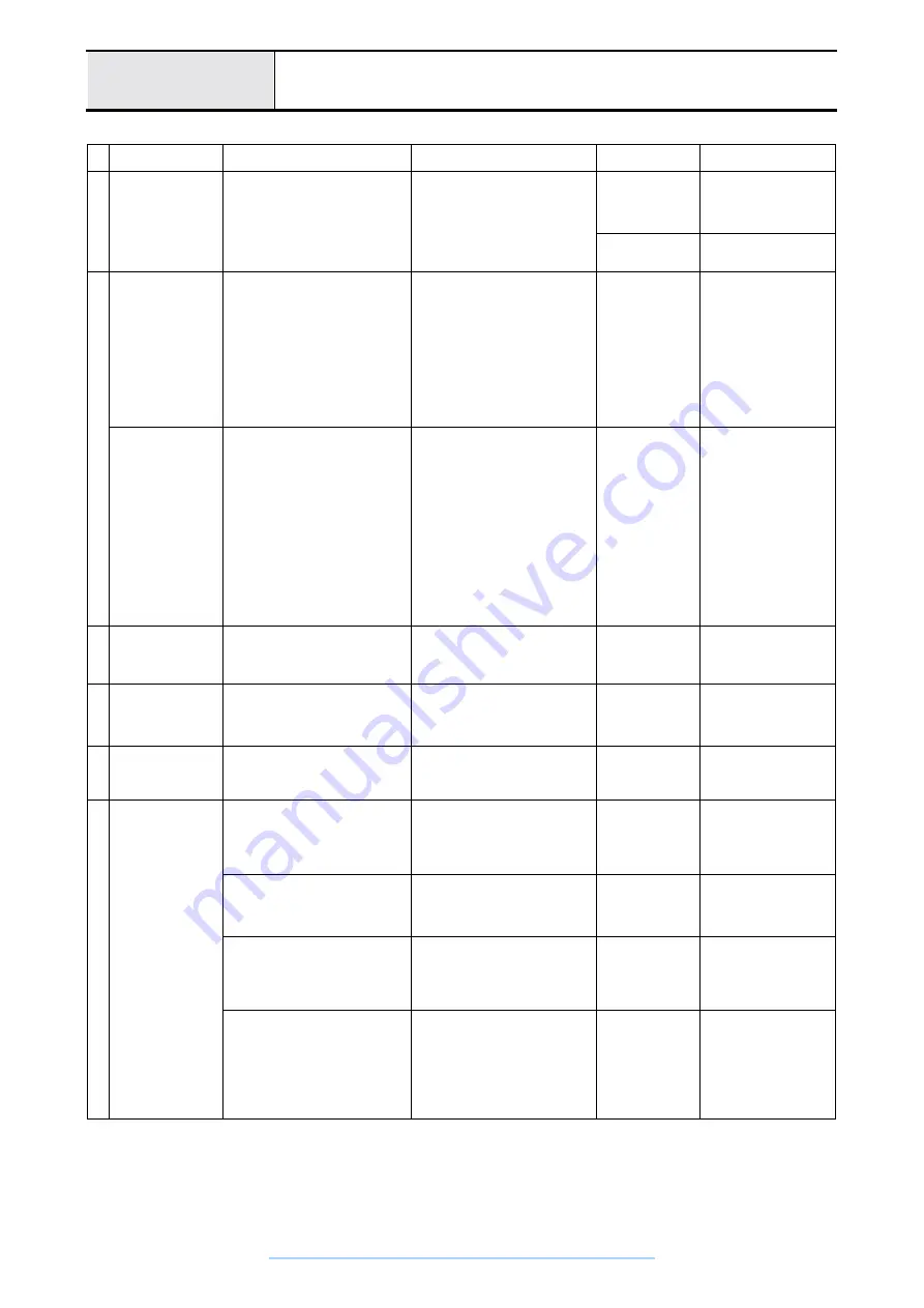
Problem
Primary factors and causes
Repair method
Items for
Inspection
Inspection method and
standards
1
Stitch skipping
Thread fraying
Thread breakage
Seam unevenness
Needle breaks
Needle tip smashed during sewing
Needle catches and bends before or
after sewing.
Needle replacement
Needle curvature
Remove the needle, place
on level block (horizontal
block) and be sure there is
no curvature.
Needle smashed
Touch the needle tip with
your finger, be sure that it
is not smashed.
2
Nothing displays on
LCD with power ON
or 7-SEG LED
Inlet connector disconnection
Plug connector in
Sewing machine
runs when switched
on
When the power is turned
on
there is a beep and the
LCD or 7-SEG LED is
displayed
Bad power supply unit S
Replace power supply unit S
Fuse in power supply unit S is burned
out
Replace power supply unit S fuse
Connector between power supply unit
S and main PCB disconnected
Plug connector in
Bad main PCB
Replace main PCB assy.
Connector between main PCB and
SS-VR PCB disconnected
Plug connector in
Bad contrast adjustment
Adjust contrast
Main lamp (LED
lamp) does not light
(machine operation
normal)
Bad LED lamp SR
LED lamp SR lead wire disconnect
Replace LED lamp SR assy.
Bad LED lamp SL
LED lamp SL lead wire disconnect
Replace LED lamp SL assy.
LED lamp SR connector disconnect
Plug connector in
LED lamp SL connector disconnect
Plug connector in
Bad main PCB
Replace main PCB assy.
Bad operation PCB
Replace operation PCB assy.
Bad SS-VR F PCB
Replace SS-VR F PCB
Selection switch always on
Reassemble bad switch
¦
Since two LED lamps are
connected in series, two go out
with one broken wire
3
Cassette display lamp
(green, red) does not
light
Bad cassette switch
Replace cassette switch
Display lamp lights with no
cassette inserted
Cassette switch connector
disconnection
Plug cassette switch connector in
Bad main PCB
Replace main PCB assy.
4
Even when the
presser is raised with
a straight line pattern,
the sewing machine
will not run.
Bad presser switch adjustment
Adjust presser switch position
Presser switch
function
Bad presser switch
Replace presser switch
5
Straight line left base
line sewing
unevenness
(pitch)
Bad left-right needle drop adjustment
Bad left-right needle drop adjustment
Three point drop
(divide left and
right)
Needle should be in the
average right-left position
with respect to the needle
plate needle hole
Loose drop adjustment eccentric
screw
Bad left-right needle drop adjustment
6
Stitch skipping, thread
abrasion
Thread breakage
Bad needle interference adjustment
Needle and tip gap
Lightly press the lower part
(cover part) of the SS
button while running on the
right base line, and check
for the faint sound of the
needle and tip hitting.
Loose needle interference adjustment
screw
Bad front-back needle drop
adjustment
Readjust front-back needle drop
Front-back needle
drop position
Turn the pulley by hand,
and confirm that there is a
gap with the needle before
and after the needle plate
groove.
Bad needle plate attachment position
Reattach the needle plate
Bad needle bar rise adjustment
Adjust needle bar rise
Needle bar rise
amount for needle
and rotary hook
meeting
With a 2.9 – 3.3 mm rise
from the lowest point for
the needle, the tip of the
bobbin should come to the
left side of the needle.
(measure with gauge)
Loose timing adjustment screws
Readjust needle and rotary hook
meeting
Bad needle bar height adjustment
Adjust needle bar height
Needle bar height
When the needle and
outside of the bobbin tip
meet when turning the
pulley on the left base line,
the distance from the top of
the needle hole to the
bottom of the bobbin tip
should be 1.0 –1.4 mm.
Loose timing adjustment screws
Adjust needle bar height
www.promelectroavtomat.ru
Содержание CS8000 Series
Страница 1: ...www promelectroavtomat ru ...
Страница 2: ...www promelectroavtomat ru ...
Страница 10: ...viii www promelectroavtomat ru ...
Страница 22: ...2 2 Main partslocation diagram Main unit www promelectroavtomat ru ...
Страница 27: ...2 7 Disassembly Front coverlocation diagram CS8000 Series CS8100 Series Main unit www promelectroavtomat ru ...
Страница 38: ...2 18 Upper shaft mechanismlocation diagram Main unit www promelectroavtomat ru ...
Страница 45: ...2 25 Disassembly Thread tension mechanismlocation diagram Main unit www promelectroavtomat ru ...
Страница 53: ...2 33 Disassembly Thread hook mechanism location diagram Main unit www promelectroavtomat ru ...
Страница 56: ...2 36 Needle presser module breakout diagram Modules www promelectroavtomat ru ...
Страница 65: ...2 45 Disassembly Feed module breakout diagram Modules www promelectroavtomat ru ...
Страница 74: ...3 2 Thread tension mechanism location diagram Main unit www promelectroavtomat ru ...
Страница 85: ...3 13 Assembly Thread hook mechanism location diagram Main unit www promelectroavtomat ru ...
Страница 88: ...3 16 Upper shaft mechanism location diagram Main unit www promelectroavtomat ru ...
Страница 107: ...3 35 Assembly Front cover location diagram CS8000 Series CS8100 Series Main unit www promelectroavtomat ru ...
Страница 115: ...3 43 Assembly Main parts location diagram Main unit www promelectroavtomat ru ...
Страница 120: ...3 48 Needle presser modulebreakout diagram Modules www promelectroavtomat ru ...
Страница 136: ...3 64 Feed module breakout diagram Modules www promelectroavtomat ru ...
Страница 201: ...6 1 6Repair Manual www promelectroavtomat ru ...
Страница 207: ...www promelectroavtomat ru ...
Страница 208: ...www promelectroavtomat ru ...