background image

4-5

Confidential

1.2 Initialization of EEPROM of Main PCB ASSY 

(Maintenance Mode: Code 01)

Initialize the EEPROM in accordance with 

"1.4.1 EEPROM parameter initialization" in Chapter 5

.

1.3 Setting by Country (Maintenance Mode: Code 74)

Make appropriate settings by country in accordance with

 "1.4.26 Setting by country" in 

Chapter 5

.

1.4 Setting the Serial Number

<Procedures>

(1) Connect the PC and machine with the USB cable.
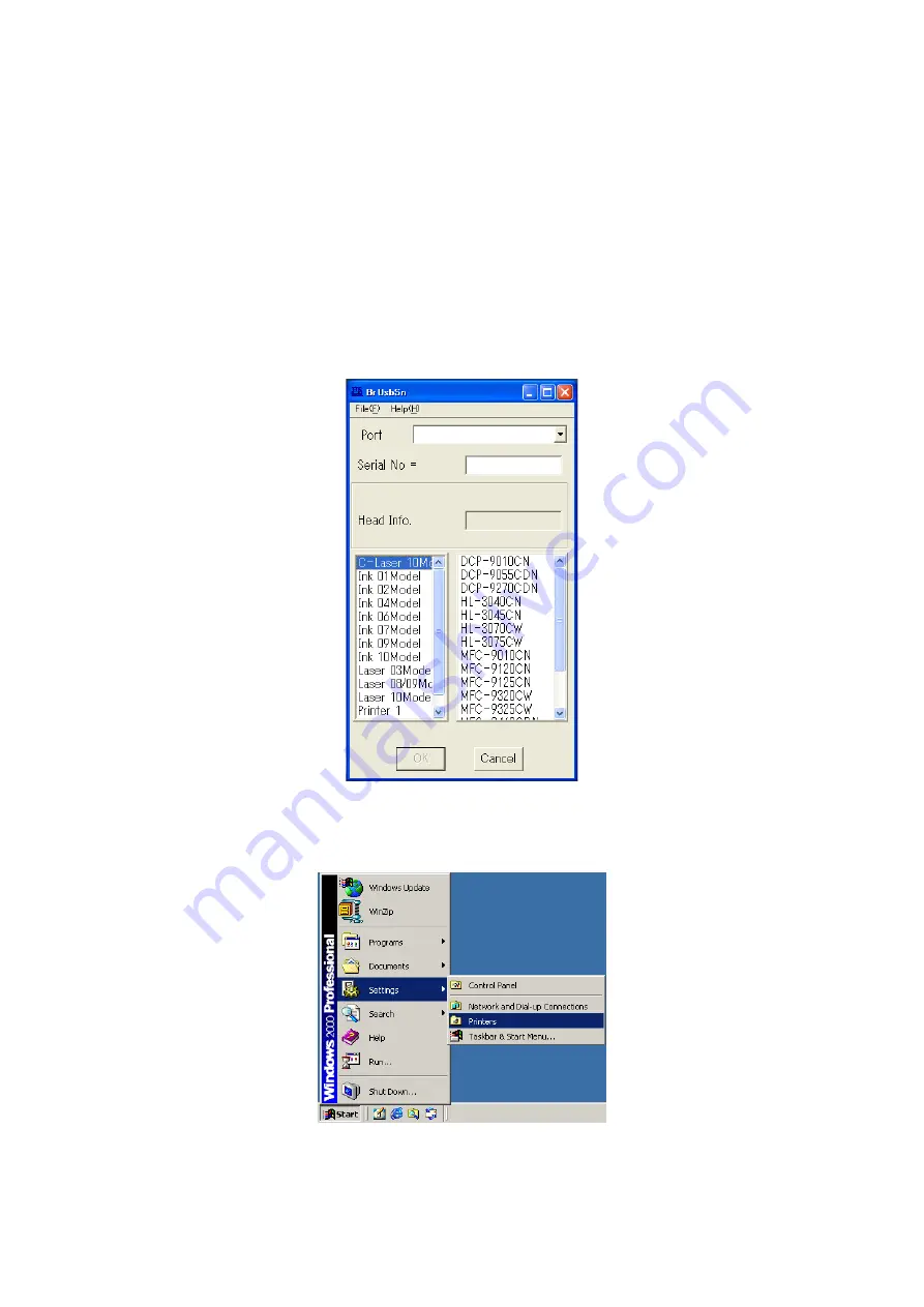
(2) Double-click the brusbsn.exe file which has been copied in the temporary folder to start.

(3) Click the C-Laser 10Model.
(4) In Port on the brusbsn screen, select the port number assigned to the Brother 

Maintenance USB Printer. If the port number is unknown, follow steps below.
1) Click Start | Settings | Printers.

Содержание 09055CDN

Страница 1: ...1 4 Brother Color Laser MFC SERVICE MANUAL MODEL DCP 9055CDN 9270CDN MFC 9460CDN 9465CDN MFC 9560CDW 9970CDW Read this manual thoroughly before maintenance work Keep this manual in a convenient place for quick and easy reference at all times ...

Страница 2: ...demarks of Citrix Systems Inc in the United States Intel Intel Xeon and Pentium are trademarks or registered trademarks of Intel Corporation AMD AMD Athlon AMD Opteron and combinations thereof are trademarks of Advanced Micro Devices Inc PictBridge is a trademark Each company whose software title is mentioned in this manual has a Software License Agreement specific to its proprietary programs All ...

Страница 3: ...a 1 10 1 7 Telephone 1 10 1 8 FAX Only for the models with FAX function 1 10 1 9 Copy 1 11 1 10 Scanner 1 12 1 11 Unscannable Area 1 13 1 12 USB Direct Interface 1 13 CHAPTER 2 ERROR INDICATION AND TROUBLESHOOTING 1 INTRODUCTION 2 1 1 1 Precautions 2 1 1 2 Initial Check 2 2 2 OVERVIEW 2 4 2 1 Cross section Drawing 2 4 2 2 Paper Feeding 2 7 2 3 Operation of Each Part 2 10 2 4 Block Diagram 2 12 2 5...

Страница 4: ...g Problems 2 128 3 9 1 No feeding 2 128 3 9 2 Double feeding 2 128 3 9 3 Paper jam 2 129 3 9 4 Wrinkles 2 130 3 10 Scanning Image Defect Troubleshooting 2 131 3 10 1 Image defect examples 2 131 3 10 2 Troubleshooting image defect 2 131 3 11 Troubleshooting of the Control Panel 2 134 3 11 1 Nothing is displayed on the LCD 2 134 3 11 2 The control panel does not work 2 134 3 11 3 Lamp malfunction 2 ...

Страница 5: ...G 3 2 3 SCREW CATALOGUE 3 3 4 SCREW TORQUE LIST 3 4 5 LUBRICATION 3 7 6 OVERVIEW OF GEARS 3 9 7 HARNESS ROUTING 3 11 8 DISASSEMBLY FLOW 3 28 9 DISASSEMBLY PROCEDURE 3 30 9 1 Paper Tray 3 32 9 2 Back Cover Back Cover Stopper Arm L R 3 33 9 3 Fuser Cover 3 36 9 4 Fuser Unit 3 38 9 5 Side Cover L Access Cover 3 41 9 6 Side Cover R ASSY 3 47 9 7 Duplex Feed ASSY 3 51 9 8 MP Cover ASSY MP Paper Guide A...

Страница 6: ...cument Cover ASSY Grip Cover 3 113 9 32 Panel Cover ASSY 3 114 9 33 Panel Unit 3 115 9 34 Panel PCB ASSY 3 118 9 35 Rubber Key 3 121 9 36 LCD Back Light Module Touch Panel PCB ASSY Touch Panel ASSY 3 124 9 37 Pull Arm Guide Lock Claw A4 Model Only 3 128 9 38 Joint Cover Top 3 129 9 39 NCU PCB ASSY 3 134 9 40 Back Cover Upper A4 Model Only 3 136 9 41 Joint Cover FL ASSY 3 137 9 42 USB Host Relay PC...

Страница 7: ...ler Holder 3 186 9 71 Registration Mark Sensor Holder ASSY Shutter Solenoid 3 188 9 72 MP Paper Empty Registration Front Sensor PCB ASSY 3 191 9 73 PF ASSY 3 199 9 74 T1 Registration Front Rear Sensor PCB ASSY 3 202 9 75 MP Sector Solenoid 3 203 9 76 T1 Paper Edge Sensor PCB ASSY T1 Paper Edge Actuator T1 Paper Edge Actuator Spring 3 204 9 77 Cleaner Drive Gear 15 3 206 9 78 High voltage Power Sup...

Страница 8: ...ly 4 7 1 10 Operation Check of Sensors Maintenance Mode Code 32 4 7 2 IF YOU REPLACE THE REGISTRATION MARK SENSOR HOLDER ASSY 4 8 2 1 Sensitivity Adjustment of Density Sensor Maintenance Mode Code 72 4 8 2 2 Performing the Developing Bias Voltage Correction Maintenance Mode Code 83 4 8 2 3 Performing the Adjustment of Inter color Position Alignment Maintenance Mode Code 66 4 8 3 IF YOU REPLACE THE...

Страница 9: ...stment of Touch Panel Maintenance Mode Code 61 Touch Panel Model Only 4 16 11 IF YOU REPLACE THE SECOND SIDE SCANNING CIS DUPLEX SCANNING MODEL 4 17 11 1 Acquisition of White Level Data Maintenance Mode Code 55 4 17 11 2 Scanning and Printing Check 4 17 11 3 Placement of Document Scanner Unit in Position for Transportation Maintenance Mode Code 06 4 17 12 IF YOU REPLACE THE ADF UNIT 4 17 12 1 Acqu...

Страница 10: ...Function code 66 5 42 1 4 20 Continuous print test Function code 67 5 46 1 4 21 Laser unit test pattern print Function code 68 5 49 1 4 22 Frame pattern print One sided Function code 69 5 50 1 4 23 Frame pattern print Two sided Function code 70 5 51 1 4 24 Color test pattern Function code 71 5 52 1 4 25 Sensitivity adjustment of density sensor Function code 72 5 54 1 4 26 Setting by country Functi...

Страница 11: ...RIODICAL REPLACEMENT PARTS 7 2 2 1 Procedures to Replace Periodical Replacement Parts 7 2 2 1 1 Fuser unit 7 3 2 1 2 Laser unit 7 11 2 1 3 Paper feeding kit1 7 48 2 1 4 Paper feeding kit2 7 51 2 1 5 MP paper feeding kit 7 54 APPENDIX 1 SERIAL NUMBERING SYSTEM APPENDIX 2 DELETION OF USER SETTING INFORMATION ETC APPENDIX 3 INSTALLING THE MAINTENANCE DRIVER ...

Страница 12: ...iance with the essential requirements of Directives 1999 5 EC and 2005 32 EC The Declaration of Conformity DoC is on our Website Please go to http solutions brother com choose region eg Europe choose country choose your model choose Manuals choose Declaration of Conformity Select Language when required Declaration of Conformity Europe only DCP 9055CDN only We Brother Industries Ltd 15 1 Naeshiro c...

Страница 13: ...ff power completely Wiring Information U K only If you need to replace the plug fuse fit a fuse that is approved by ASTA to BS1362 with the same rating as the original fuse Always replace the fuse cover Never use a plug that does not have a cover If in any doubt call a qualified electrician Warning This product must be earthed The wires in the mains lead are coloured in line with the following cod...

Страница 14: ... with the above recycling symbol It means that at the end of the life of the equipment you must dispose of it separately at an appropriate collection point and not place it in the normal domestic unsorted waste stream This will benefit the environment for all European Union only ...

Страница 15: ...es cause harmful interference to radio or television reception which can be determined by turning the equipment off and on the user is encouraged to try to correct the interference by one or more of the following measures Reorient or relocate the receiving antenna Increase the separation between the equipment and receiver Connect the equipment into an outlet on a circuit different from that to whi...

Страница 16: ...l covers the laser beam cannot escape from the machine during any phase of user operation FDA Regulations 110 to 120 volt model only The USA Food and Drug Administration FDA has implemented regulations for laser products manufactured on and after August 2 1976 Compliance is mandatory for products marketed in the United States The following label on the back of the machine indicates compliance with...

Страница 17: ...sible personal injury Electrical Hazard icons alert you to a possible electrical shock Hot Surface icons warn you not to touch machine parts that are hot Cautions specify procedures you must follow or avoid to prevent possible damage to the machine or other objects Note Notes tell you useful tips when servicing the machine Memo Memo tells you bits of knowledge to help understand the machine ...

Страница 18: ...machine or replace parts make sure that you have turned off the power switch and unplugged the machine from the AC power outlet DO NOT handle the plug with wet hands Doing this might cause an electrical shock The fuser unit becomes extremely hot during operation Wait until it has cooled down sufficiently before replacing consumable items DO NOT remove or damage the caution label located on or arou...

Страница 19: ...Doing this may cause a fire or electrical shock If the machine becomes hot blows smoke or generates obscure odor immediately turn off the power switch and unplug the machine from the AC power outlet If metal objects water or other liquids get inside the machine immediately turn off the power switch and unplug the machine from the AC power outlet This machine is heavy and weighs approximately 28 0 ...

Страница 20: ...mage this product We recommend that you use a quality surge protection device on the AC power line or unplug the machine during a lightning storm Violently closing the front cover without mounting the toner cartridge and the drum unit can damage this product ...

Страница 21: ...rmanently damage the eyes Since the beam is invisible the following caution label is attached on the laser unit CAUTION When the machine during servicing is operated with the cover open the regulations of VBG 93 and the performance instructions for VBG 93 are valid CAUTION In case of any trouble with the laser unit replace the laser unit itself To prevent direct exposure to the laser beam do not t...

Страница 22: ...Confidential CHAPTER 1 SPECIFICATIONS ...

Страница 23: ...al 1 1 1 2 Network Connectivity 1 6 1 3 Service Information 1 7 1 4 Supplies 1 8 1 5 Paper 1 9 1 5 1 Paper handling 1 9 1 5 2 Media specifications 1 9 1 6 Unprintable Area 1 10 1 7 Telephone 1 10 1 8 FAX Only for the models with FAX function 1 10 1 9 Copy 1 11 1 10 Scanner 1 12 1 11 Unscannable Area 1 13 1 12 USB Direct Interface 1 13 ...

Страница 24: ...me 1 Monochrome Less than 16 seconds Color Less than 16 seconds CPU StarSaphire SS1000 400 MHz Memory 128 MB 256 MB Interface Hi Speed USB 2 0 10BASE T 100BASE TX Ethernet Power consumption Peak 1 200 W Copying For U S A Average Approximately 575 W Except for U S A Average Approximately 570 W Approximately 615 W Ready Average Approximately 70 W Average Approximately 75 W Sleep Wireless LAN ON N A ...

Страница 25: ... to 28 30 ppm A4 Let ter size When loading A4 or Letter size paper from the paper tray Two sided Monochrome Full Color Up to 7 7 ppm A4 Letter size When loading A4 or Letter size paper from the paper tray Warm up time From Sleep mode Less than 33 seconds From Power OFF ON Less than 35 seconds 23 C 73 4F First print time 1 Monochrome Less than 16 seconds Color Less than 16 seconds CPU StarSaphire S...

Страница 26: ...Storage 0 to 40 C Humidity Operating 20 to 80 Storage 10 to 90 Dimensions W x D x H Carton Size 585 x 676 x 660 mm 23 0 x 26 6 x 26 0 inch 663 x 699 x 694 mm 26 1 x 27 5 x 27 3 inch Machine Size 410 x 503 x 492 mm 16 1 x 19 8 x 19 4 inch 490 x 526 x 530 mm 19 3 x 20 7 x 20 9 inch Weights With Carton 32 0 kg 70 5 lb 34 0 kg 75 0 lb Without Carton With toner drum 26 5 kg 58 4 lb 28 5 kg 62 8 lb With...

Страница 27: ...nal X64 Edition 1 4 64 bit Intel 64 or AMD64 supported CPU 256 MB 512 MB Windows Vista 4 Intel Pentium 4 Or equivalent 64 bit Intel 64 or AMD64 supported CPU 512 MB 1 GB 500 MB 1 2 GB Windows 7 4 1 GB 32 bit 2 GB 64 bit 1 GB 32 bit 2 GB 64 bit 650 MB Windows Server 2003 print only via network Intel Pentium III or equivalent 256 MB 512 MB 50 MB N A 10BASE T 100BASE TX Ethernet Wireless 802 11 b g W...

Страница 28: ...dows XP and SP2 or higher for Windows Vista and Windows 7 Specifications are subject to change without notice Computer platform operating system version Processor Speed Minimum RAM Recom mended RAM Available Hard Disk Space Supported PC Interface 2 For Drivers For Applications Macintosh Operating System Mac OS X 10 4 11 10 5 x PowerPC G4 G5 Intel CoreTM Processor 512 MB 1GB 80 MB 400 MB USB 10BASE...

Страница 29: ...Network security N A Model MFC 9460CDN MFC 9465CDN MFC 9560CDW MFC 9970CDW Wired network Network node type NC 6900h type2 Network type 10BASE T 100BASE TX Ethernet Network security APOP POP before SMTP SMTP AUTH SSL TLS IPPS HTTPS SMTP POP SNMP v3 802 1x EAP MD5 EAP FAST PEAP EAP TLS EAP TTLS Kerberos Wireless network Network node type N A IEEE802 11b g Infrastructure Mode Adhoc mode RF channels N...

Страница 30: ...proximately 200 000 pages A4 Letter or 5 years Machine life ADF 50 000 pages or 5 years Machine life Document scanner unit 50 000 pages or 5 years MTBF 4 000 hours MTTR 0 5 hours Maximum monthly print volume Touch panel model 60 000 pages Non Touch panel model 40 000 pages Periodical replacement parts Fuser unit 100 000 pages or 5 years Laser unit Paper feeding kit1 Paper feeding kit2 Paper feedin...

Страница 31: ...d pages in accordance with ISO IEC 19798 Shelf life 2 years without opening 6 months after opening Drum unit Life expectancy Approximately 25 000 pages drum unit The life expectancy varies according to the use condition Refer to Display of the machine log Function code 80 in Chapter 5 When printing A4 Letter size one sided pages in accordance with ISO IEC 19798 Shelf life 2 years without opening T...

Страница 32: ... Paper tray 2 Plain Paper Thin Paper Recycled Paper MP tray Plain Paper Thin Paper Thick Paper Thicker Paper Recycled Paper Bond Label Envelope Env Thin Env Thick Glossy Paper 1 Duplex Plain Paper Thin Paper Recycled Paper Glossy Paper ADF Plain Paper Recycled Paper Media weight Paper tray 1 60 to 105 g m2 16 to 28 lb Paper tray 2 60 to 105 g m2 16 to 28 lb MP tray 60 to 163 g m2 16 to 43 lb Duple...

Страница 33: ...a that cannot be printed on may vary depending on the paper size and the printer driver you are using The unprintable area shown above is for Letter size paper Model All models Handset N A Model MFC 9460CDN MFC 9465CDN MFC 9560CDW MFC 9970CDW Modem Speed 33 600 bps FAX Transmission speed Approximately 2 5 seconds ITU Test Chart Std resolution JBIG ITU T group Super G3 Color FAX Sending Yes Not ava...

Страница 34: ... Tray Color Less than 21 seconds from Ready mode and standard Tray Resolution Optical Up to 1200 main scanning x 600 dpi sub scanning Auto duplex scanning copy N A Yes Model MFC 9460CDN MFC 9465CDN MFC 9560CDW MFC 9970CDW Copy Speed simplex FB ADF Monochrome Up to 24 25 cpm A4 Letter Up to 28 30 cpm A4 Letter Color First copy out time Monochrome Less than 19 seconds from Ready mode and standard Tr...

Страница 35: ...nning 19 200 main scanning x 19 200 dpi sub scanning Scanning speed Monochrome Color A4 2 12 seconds Letter 1 99 seconds A4 1 79 seconds Letter 1 68 seconds Model MFC 9460CDN MFC 9465CDN MFC 9560CDW MFC 9970CDW Resolution Optical FB Maximum scanning 1 200 main scanning x 2 400 dpi sub scanning ADF Maximum scanning 1 200 main scanning x 600 dpi sub scanning Resolution Interpolated Maximum scanning ...

Страница 36: ...tter 4 mm 0 16 inch 3 96 mm 0 15 inch A4 4 mm 0 16 inch 3 mm 0 12 inch Note For copies This unprintable area shown above is for a single copy or a 1 in 1 copy using A4 size paper The area that cannot be printed on may vary depending on the paper size Model DCP 9055CDN DCP 9270CDN PictBridge N A Direct print N A PDF version1 7 JPEG Exif JPEG PRN created by own printer driver TIFF scanned by Brother...

Страница 37: ...Confidential CHAPTER 2 ERROR INDICATION AND TROUBLESHOOTING ...

Страница 38: ...tial Check 2 2 2 OVERVIEW 2 4 2 1 Cross section Drawing 2 4 2 2 Paper Feeding 2 7 2 3 Operation of Each Part 2 10 2 4 Block Diagram 2 12 2 5 Components 2 13 2 6 Life of Toner Cartridge and Drum Unit 2 14 3 ERROR INDICATIONS 2 17 3 1 Error Codes 2 17 3 2 Error Messages 2 24 3 3 Communications Error Code 2 29 3 4 Error Cause and Remedy 2 32 3 5 Paper Feeding Problems 2 103 3 5 1 No feeding 2 103 3 5...

Страница 39: ... only 2 135 3 12 Troubleshooting of FAX Functions 2 136 3 12 1 FAX can t send it 2 136 3 12 2 Speed dialing and One touch dialing can t be used 2 136 3 12 3 FAX cannot be received 2 137 3 12 4 No bell ring 2 137 3 12 5 Speaker is silent during On hook dialing 2 137 3 12 6 Dialing function does not switch between Tone and Pulse 2 138 3 12 7 A communication error occurs 2 138 3 12 8 Reception mode c...

Страница 40: ...When connecting or disconnecting cable connectors make sure that you hold the connector body and not the cables 3 Static electricity charged in your body may damage electronic parts Before handling the PCBs touch a metal portion of the machine to discharge static electricity charged in your body When transporting PCBs be sure to wrap them in conductive sheets When replacing the PCBs put on a groun...

Страница 41: ...sture or dust 4 Keep the machine horizontal when you carry it To prevent injuries when moving or lifting this machine make sure to use at least two people Fig 2 1 Power supply 1 The AC input power supply described on the rating plate of the machine should be within 10 of the rated voltage 2 The AC input power supply is within the regulated value 3 The cables and harnesses are connected correctly 4...

Страница 42: ...urs to allow it to reach room temperature If the drum unit is unpacked soon after it is moved from a cold place to a warm room condensation may occur inside the unit which may cause incorrect images Instruct the user to allow the unit to come to room temperature before unpacking it This will take one or two hours 2 Low temperature The motor may not drive normally under the low temperature environm...

Страница 43: ...Duplex feed ASSY DX feed roller DX feed roller Belt unit T1 paper edge actuator MP paper empty actuator T1 paper pick up roller T1 separation pad T1 separation roller Registration rear actuator MP separation roller MP paper pick up roller Registration front actuator MP separation pad MP registration front actuator Registration roller Front Exposure drum Black Exposure drum Yellow Paper eject rolle...

Страница 44: ...ar actuator Document sponge Ejection roller Exit pinch roller FB glass First side document hold First side scanning CIS Flap ADF BC Document feed Document feed Pinch roller Pressure Document second side rear sensor Second side document hold Scanner Separate roller Document pull in roller Document pull in roller holder Paper guide Pinch roller Second side scanning CIS Separation rubber side rear ac...

Страница 45: ...h roller FB glass First side document hold First side scanning CIS Flap ADF BC Document feed Pinch roller Second side Scanner Separate roller Document pull in roller Document pull in roller holder Paper guide Pinch roller Second side scanning CIS Separation rubber side rear actuator top cover Pressure Document first side rear sensor Document second side rear sensor roller ADF open actuator documen...

Страница 46: ...2 7 Confidential 2 2 Paper Feeding Printer part Fig 2 5 Paper eject from the back side DX path Paper tray 1 path Paper feed from the MP tray Front Back side ...

Страница 47: ...2 8 Confidential ADF part A4 model Fig 2 6 Left side Right side Document feed path Face up ...

Страница 48: ...2 9 Confidential ADF part Legal model Fig 2 7 Left side Right side Document feed path Face up ...

Страница 49: ...the paper to the paper eject roller 1 Paper eject actuator Detect whether or not paper is ejected from the fuser unit In the case of the duplex printing detect the rear edge of paper and adjust the timing of the paper eject roller 2 and 3 switching Paper eject roller 1 Feed the paper ejected from the fuser unit to the paper eject roller 2 Paper eject roller 2 Feed the paper to the paper eject roll...

Страница 50: ...e the documents fed by the document pull in roller into a single paper Document second side rear actuator Detect the front edge of the paper and adjust the scanning position of the second side Detect paper jam in the ADF Document feed roller Feed the paper to the CIS unit first side Document first side rear actuator Detect the front edge of the paper and adjust the scanning position of the first s...

Страница 51: ... edge sensor PCB Belt unit temperature sensor Speaker NCU PCB FAX model only Back light module LCD Panel PCB Registration mark R PCB Registration mark L PCB Wireless LAN PCB Wireless LAN model only USB host model only USB host relay PCB Internal temperature sensor Center thermistor Paper eject sensor PCB Side thermistor Low voltage power supply PCB T2 sensor PCB T2 Relay PCB ASSY T2 registration s...

Страница 52: ...y unit Power fan PCB ASSY Registration mark Waste toner box Belt unit Drum unit Toner cartridge sensor holder ASSY ADF unit Panel unit Joint cover Joint cover top Document MP paper PF cleaner drive ASSY Wireless LAN guide ASSY ASSY ASSY base ASSY MP upper cover ASSY Side cover Side cover L ADF unit Panel unit Joint cover top Joint cover base ASSY Back cover Legal model A4 model ASSY A4 model Leagl...

Страница 53: ...the table below At the point of in the figure above To avoid problems caused by the worn out of the developer roller surface and deterioration of the toner ceiling Replace Toner message is displayed and the print operation is prohibited when the number of the rotations of the developer roller reaches the upper limit even if toner remains The upper limit of the number of the rotations of the develo...

Страница 54: ...provided in this page are as of August 2010 These values are subject to change without prior notice Average print page page job 1 2 3 4 5 6 7 8 Cartridge life Standard K 1 750 2 762 3 421 3 885 4 229 4 494 4 705 4 876 Cartridge life Standard YMC 1 050 1 640 2 018 2 281 2 474 2 622 2 739 2 834 Cartridge life High K 2 800 4 419 5 474 6 216 6 766 7 190 7 528 7 802 Cartridge life High YMC 2 450 3 827 ...

Страница 55: ...d or later page printed x Number of pages in continuous printing 1 24 The number of drum rotations per one page continuous printing Example Starts to print when the machine is in the Ready state If you leave the machine without printing for a long time the number of drum rotations is increasing because the developing bias voltage correction and the color registration are performed If you print one...

Страница 56: ...16 Paper of unsupported size for duplex printing or paper of different sizes is loaded 2 34 17 The paper tray 1 is not installed before printing The cassette of the T1 paper edge sensor is open 2 35 18 The paper tray 2 is not installed before printing The cassette of the T2 paper edge sensor is open 2 35 19 The drum unit reached the end of life 2 36 1A Condensation occurred on the laser unit 2 36 ...

Страница 57: ...or error 2 45 38 External temperature sensor error 2 45 39 External humidity sensor error 2 45 Error codes Problem Refer to 3A Engine PCB transfer error Communication error between the main CPU and sub CPU 2 45 3B Main PCB DRAM access error 2 46 3C Main PCB error Write error in NVRAM 2 46 3D Main PCB error Read error in NVRAM 2 46 3E Main PCB error Bus error in NVRAM 2 46 3F Write error in engine ...

Страница 58: ...at the length of the paper under printing was less than the specified value 2 53 Error codes Problem Refer to 5C It was detected that the size of the paper was less than the specified value 2 53 5D The belt unit will reach the end of life soon 2 53 5E Belt unit is at the end of life 2 53 5F The waste toner box near full The sensor detected that the waste toner became near full 2 54 60 Cyan toner c...

Страница 59: ... sharp temperature rise 2 60 78 Fuser unit error The center thermistor detects the sharp temperature fall 2 60 Error codes Problem Refer to 7A Engine PCB error detection of PF drive motor lock error 2 60 7B Engine PCB error 2 61 7C Communication error between the engine PCB and main PCB 2 61 7D Dirt on drum unit 2 61 7E Belt unit is at the end of life The operation is stopped 2 64 7F FAX paper siz...

Страница 60: ...P tray MP paper empty sensor fails to be turned ON 2 74 Error codes Problem Refer to 9D Detection of incorrect registration sensor measurement value when implementing adjustment of inter color position alignment 2 75 9E Toner of the color which is being used reaches the end of life when implementing adjustment of inter color position alignment 2 75 9F No paper is loaded 2 76 A0 Timeout error durin...

Страница 61: ...ltage failure at Low side 2 84 B9 Scanning light adjustment error 2 84 Error codes Problem Refer to BA Scanning outside light detection error 2 84 BB White level data error 2 85 BC Scanning failure upon FAX transmission Second side Document scanner unit failure for the second time or later 2 85 BD Black level data error 2 85 BE The scanning area start edge detection error 2 85 BF The document is t...

Страница 62: ...on data error upon scanning 2 96 Error codes Problem Refer to EB Read error in EEPROM of the laser unit 2 97 EC Fuser fan error 2 97 ED Communication with the wireless LAN PCB cannot be established upon startup of the power supply 2 97 EE Unavailability of communication after connecting to the wireless LAN PCB is detected 2 98 EF The supplied power is unstable 2 98 F0 USB flash memory does not wor...

Страница 63: ...er cartridge C0 2 86 Failure to detect a new yellow toner cartridge C1 2 86 Failure to detect a new magenta toner cartridge C2 2 86 Failure to detect a new cyan toner cartridge C3 2 86 Condensation Condensation occurred on the laser unit 1A 2 36 Connection Error Connection Fail FAX communication error 2 140 Cooling Down Cooling down the inside of the machine to protect it 75 2 60 Cover is Open The...

Страница 64: ... Tray 2 Paper jam in the paper tray 2 8B 2 70 Log Access Error Authentication error occurs 2 127 File access error occurs 2 127 Server timeout occurs 2 127 Server time cannot be obtained when SNTP is used 2 127 Low temperature Room temperature is low 2 140 No Belt Unit The belt unit is not installed CB 2 89 No Drum Unit The drum unit is not installed CD 2 90 No HUB Support USB HOST connection erro...

Страница 65: ...33 Inter color position alignment adjustment failure Toner of the color which is being used reached the end of life 11 2 33 Inter color position alignment adjustment failure Incorrect measurement value of inter color position alignment adjustment 12 2 34 Error in the adjustment of inter color position alignment result when implementing it 8E 2 72 Detection of incorrect registration sensor measurem...

Страница 66: ...f scanning error A5 BF 2 79 2 86 Self Diagnostic Fuser unit error After the error code 58 occurred a failure in the fuser unit is detected again upon start up 59 2 52 Short paper It was detected that the length of the paper under printing was less than the specified value 5B 2 53 Size Error DX Unsupported paper size is used for duplex printing 89 2 69 Small paper It was detected that the size of t...

Страница 67: ...inued because the data of the program file is incorrect 2 140 WT Box End Soon The waste toner box near full The sensor detected that the waste toner became near full 5F 2 54 The waste toner box will reach the end of life soon The belt cleaner voltage becomes lower than the specified value F2 2 99 Error message Description Error codes Refer to ...

Страница 68: ...ssion for 7 bits or more 2 138 20 04 Overrun detected 2 138 20 05 A frame for 3 seconds or more received 2 138 20 06 CRC error in answerback 2 138 20 07 Echo command received 2 138 20 08 Invalid command received 2 138 20 09 Command ignored once for document setting or for dumping out at turn around transmission 2 138 20 0A T5 time out error 2 138 20 0B CRP received 2 138 20 0C EOR and NULL receive...

Страница 69: ...of background color 2 138 63 01 Password plus lower 4 digits of telephone number not coincident 2 138 63 02 Password not correct 2 138 63 03 Polling ID not correct 2 138 74 DCN received 2 138 80 01 Fallback impossible 2 138 90 01 Unable to detect video signals and commands within 6 seconds after CFR is transmitted 2 138 90 02 Received PPS containing invalid page count or block count 2 138 A0 03 Er...

Страница 70: ...n before establishment of FAX communication 2 2 138 BF 02 Communication canceled by pressing the Stop Exit button after establishment of FAX communication 2 2 138 BF 03 Transmission canceled due to a scanning error caused by no document or document feed problem in ADF scanning in real time transmission 2 138 C0 01 No common modulation mode or failed to poll 2 138 C0 02 Unable to detect JM 2 138 C0...

Страница 71: ... cover sensor is OFF User Check Close the back cover Step Cause Remedy 1 Harness connection failure of LCD unit Check the harness connection of the LCD unit and reconnect it 2 LCD unit failure Replace the touch panel ASSY 3 Main PCB failure Replace the main PCB ASSY Duplex Disabled Close the Back Cover of the machine Step Cause Remedy 1 Harness connection failure of back cover sensor Check the har...

Страница 72: ...artridge of the color displayed on the LCD Non Touch panel model Registration Registration failed Press Start and try again Touch panel model Registration failed Press Start and try again Step Cause Remedy 1 Main PCB failure Replace the main PCB ASSY Non Touch panel model Registration Registration failed Press Start and try again Touch panel model Registration failed Registration failed Press Star...

Страница 73: ...dy 1 Foreign object is affixed around the density sensor Remove the foreign object affixed around the density sensor 2 Harness connection failure of registration mark sensor holder ASSY Check the harness connection of the registration mark sensor holder ASSY and reconnect it 3 Registration mark sensor PCB failure Replace the registration mark sensor holder ASSY 4 High voltage power supply PCB fail...

Страница 74: ...CB ASSY and reconnect it 3 T1 paper edge sensor PCB failure Replace the T1 paper edge sensor PCB ASSY 4 Engine PCB failure Replace the engine PCB ASSY 5 Main PCB failure Replace the main PCB ASSY Non Touch panel model No Tray A Tray is not detected install Tray 2 Touch panel model No Tray The paper tray cannot be detected re install Tray 2 Step Cause Remedy 1 T2 paper edge actuator catching on som...

Страница 75: ...power ON After that close the front and rear covers and turn OFF and ON the power switch Replace Drum Open the Front Cover replace the Drum Unit Refer to the User s Guide for instructions Step Cause Remedy 1 Main PCB failure Replace the main PCB ASSY Condensation Leave switched ON Fully open the front cover Wait 30 minutes switch OFF and close cover then switch ON Step Cause Remedy 1 Engine PCB fa...

Страница 76: ...This error does not usually occur in the normal use The conceivable causes are noise around the installation site fluctuation of the power supply voltage and failures in the software User Check Turn OFF the power switch and turn it ON again after a while Drum Stop We cannot guarantee the print quality Replace the Drum Unit Refer to the User s Guide for instructions Drum Stop We cannot guarantee th...

Страница 77: ...ble 20 Turn the power off and then back on again Print Unable 21 Turn the power off and then back on again Print Unable 22 Turn the power off and then back on again Print Unable 23 Turn the power off and then back on again Step Cause Remedy 1 Main PCB failure Replace the main PCB ASSY Print Unable 24 Turn the power off and then back on again Step Cause Remedy 1 Harness connection failure of intern...

Страница 78: ...gain after a while Error code 27 PF drive motor error User Check Turn OFF the power switch and turn it ON again after a while Print Unable 25 Turn the power off and then back on again Step Cause Remedy 1 Main PCB failure Replace the main PCB ASSY Print Unable 26 Turn the power off and then back on again Step Cause Remedy 1 Main PCB failure Replace the main PCB ASSY Print Unable 27 Turn the power o...

Страница 79: ... Drum drive motor failure Replace the drum drive motor 3 Engine PCB failure Replace the engine PCB ASSY 4 Low voltage power supply PCB failure Replace the low voltage power supply PCB ASSY 5 Main PCB failure Replace the main PCB ASSY Print Unable 29 Turn the power off and then back on again Step Cause Remedy 1 Harness connection failure of paper eject motor Check the harness connection of the pape...

Страница 80: ...e motor and reconnect it 2 Develop release motor failure Replace the develop release motor 3 Engine PCB failure Replace the engine PCB ASSY 4 Low voltage power supply PCB failure Replace the low voltage power supply PCB ASSY 5 Main PCB failure Replace the main PCB ASSY Print Unable 2B Turn the power off and then back on again Step Cause Remedy 1 Harness connection failure of blower Check the harne...

Страница 81: ... Print Unable 2D Turn the power off and then back on again Print Unable 2E Turn the power off and then back on again Print Unable 2F Turn the power off and then back on again Step Cause Remedy 1 Toner New sensor PCB failure Check the sensor performance following the procedure described in Function code 32 If any problem occurs replace the Toner New sensor PCB ASSY 2 Engine PCB failure Replace the ...

Страница 82: ...ration mark sensor holder ASSY 3 Main PCB failure Replace the main PCB ASSY Print Unable 32 Turn the power off and then back on again Step Cause Remedy 1 Foreign object around registration mark sensor shutter Remove the foreign object 2 Harness connection failure of registration mark sensor holder ASSY Check the harness connection of the registration mark sensor holder ASSY and reconnect it 3 Harn...

Страница 83: ...ter a while Error code 36 Error in the high voltage power supply PCB while the machine is in the standby mode Print Unable 33 Turn the power off and then back on again Print Unable 34 Turn the power off and then back on again Step Cause Remedy 1 Main PCB failure Replace the main PCB ASSY Print Unable 35 Turn the power off and then back on again Step Cause Remedy 1 Engine PCB failure Replace the en...

Страница 84: ...nsor holder ASSY 3 Main PCB failure Replace the main PCB ASSY Print Unable 38 Turn the power off and then back on again Print Unable 39 Turn the power off and then back on again Step Cause Remedy 1 External temperature humidity sensor failure Replace the high voltage power supply PCB ASSY 2 High voltage power supply PCB failure Replace the high voltage power supply PCB ASSY 3 Main PCB failure Repl...

Страница 85: ...lation site fluctuation of the power supply voltage and failures in the software User Check Turn OFF the power switch and turn it ON again after a while Print Unable 3B Turn the power off and then back on again Step Cause Remedy 1 Main PCB failure Replace the main PCB ASSY Print Unable 3C Turn the power off and then back on again Print Unable 3D Turn the power off and then back on again Print Unab...

Страница 86: ...e and failures in the software User Check Turn OFF the power switch and turn it ON again after a while Print Unable 3F Turn the power off and then back on again Step Cause Remedy 1 Engine PCB failure Replace the engine PCB ASSY 2 Main PCB failure Replace the main PCB ASSY Print Unable 40 Turn the power off and then back on again Print Unable 42 Turn the power off and then back on again Step Cause ...

Страница 87: ...o Toner Open the Front Cover then install Toner Cartridge Yellow Y No Toner Open the Front Cover then install Toner Cartridge Magenta M No Toner Open the Front Cover then install Toner Cartridge Cyan C Step Cause Remedy 1 Toner New sensor PCB failure Check the sensor performance following the procedure described in Function code 32 If any problem occurs replace the Toner New sensor PCB ASSY 2 Engi...

Страница 88: ...code 4E The magenta drum unit will reach the end of life soon Error code 4F The cyan drum unit will reach the end of life soon This error does not usually occur in the normal use The conceivable causes are noise around the installation site fluctuation of the power supply voltage and failures in the software User Check Turn OFF the power switch and turn it ON again after a while Replace Drum K Rep...

Страница 89: ... is at the end of life Error code 55 Laser unit is at the end of life Replace Parts Drum Unit Replace Parts PF Kit MP Replace Parts PF Kit 1 Replace Parts PF Kit 2 Replace Parts Fuser Unit Replace Parts Laser Unit Step Cause Remedy 1 The part displayed on the LCD reached the end of life Replace the part displayed on the LCD and reset the counter of each part Refer to 2 2 Parts Life Reset Function ...

Страница 90: ...Pull out Tray 1 completely Check inside the machine or open the Back Cover to remove the jammed paper Touch panel model Animation is displayed Step Cause Remedy 1 Foreign object around paper eject Remove the foreign object 2 Foreign object around duplex feed ASSY Remove the foreign object 3 Coming off of back flapper ASSY Re assemble the back flapper ASSY 4 Duplex feed ASSY not assembled correctly...

Страница 91: ...onnector and paper eject sensor PCB ASSY Check the harness connection between the fuser unit connector and paper eject sensor PCB ASSY and reconnect it 2 Harness connection failure between fuser unit connector and low voltage power supply PCB ASSY Check the harness connection between the fuser unit connector and low voltage power supply PCB ASSY and reconnect it 3 Fuser unit failure Replace the fu...

Страница 92: ...t unit will reach the end of life soon User Check Prepare a new belt unit Error code 5E Belt unit is at the end of life User Check Prepare a new belt unit Reset the belt counter Refer to 2 2 Parts Life Reset Function in Chapter 5 Short paper Open the Back Cover and then press Start Small paper Open the Back Cover and then press Start Step Cause Remedy 1 Engine PCB failure Replace the engine PCB AS...

Страница 93: ... Soon Step Cause Remedy 1 Harness connection failure of waste toner sensor Check the harness connection of the waste toner sensor and reconnect it 2 Waste toner sensor failure Check the sensor performance following the procedure described in Function code 32 If any problem occurs replace the waste toner sensor 3 High voltage power supply PCB failure Replace the high voltage power supply PCB ASSY 4...

Страница 94: ...Replace Toner Open the Front Cover replace Toner Cartridge Yellow Y Touch panel model Animation is displayed Non Touch panel model Replace Toner Open the Front Cover replace Toner Cartridge Black K Touch panel model Animation is displayed Step Cause Remedy 1 Harness connection failure of Toner New sensor PCB ASSY Check the sensor performance following the procedure described in Function code 32 If...

Страница 95: ...able causes are noise around the installation site fluctuation of the power supply voltage and failures in the software User Check Turn OFF the power switch and turn it ON again after a while Toner Low C Prepare New Cyan C Toner Cartridge Toner Low M Prepare New Magenta M Toner Cartridge Toner Low Y Prepare New Yellow Y Toner Cartridge Toner Low K Prepare New Black K Toner Cartridge Step Cause Rem...

Страница 96: ...auses are noise around the installation site fluctuation of the power supply voltage and failures in the software User Check Turn OFF the power switch and turn it ON again after a while Print Unable 6A Turn the power off and then back on again Print Unable 6B Turn the power off and then back on again Print Unable 6C Turn the power off and then back on again Print Unable 6D Turn the power off and t...

Страница 97: ...user unit failure Replace the fuser unit 3 Low voltage power supply PCB failure Replace the low voltage power supply PCB ASSY 4 Paper eject sensor PCB failure Replace the paper eject sensor PCB ASSY 5 Main PCB failure Replace the main PCB ASSY Print Unable 70 Turn the power off and then back on again Step Cause Remedy 1 Harness connection failure of fuser develop motor Check the harness connection...

Страница 98: ...le 71 Turn the power off and then back on again Print Unable 72 Turn the power off and then back on again Print Unable 73 Turn the power off and then back on again Step Cause Remedy 1 Harness connection failure of laser unit Check the harness connections at three locations of the laser unit and reconnect them 2 Laser unit failure Replace the laser unit 3 Engine PCB failure Replace the engine PCB A...

Страница 99: ...heck Turn OFF the power switch and turn it ON again after a while Cooling Down Wait for a while Step Cause Remedy 1 Internal temperature sensor failure Replace the internal temperature sensor 2 Main PCB failure Replace the main PCB ASSY Print Unable 76 Turn the power off and then back on again Print Unable 78 Turn the power off and then back on again Step Cause Remedy 1 Fuser unit failure Replace ...

Страница 100: ...d main PCB Check the harness connection between the engine PCB ASSY and main PCB ASSY and reconnect it 2 Engine PCB failure Replace the engine PCB ASSY 3 Main PCB failure Replace the main PCB ASSY Print Unable 7C Turn the power off and then back on again Step Cause Remedy 1 Main PCB failure Replace the main PCB ASSY Non Touch panel model Drum Error Slide the Green tab on Drum Unit in each color Re...

Страница 101: ...2 62 Confidential Electrodes location of the drum unit and toner cartridge Fig 2 10 Electrodes location of the belt unit Fig 2 11 Erase lamp lens ...

Страница 102: ...ne from the AC power outlet and leave the machine for a few minutes Then wipe the electrodes above carefully with a dry lint free cloth Be careful not to change the shapes of the electrodes Developer roller Cleaning roller Belt transfer roller Belt cleaning roller Waste toner cleaner shaft Waste toner cleaner roller Paper powder cleaner Charging Corona wire Grid Erase lamp lens ...

Страница 103: ...ion of the power supply voltage and failures in the software User Check Turn OFF the power switch and turn it ON again after a while Error code 80 Fax paper size is incorrect The actually loaded paper is small User Check Use the A4 or Letter size paper Replace Belt Open the Front Cover replace the Belt Unit Step Cause Remedy 1 Main PCB failure Replace the main PCB ASSY Size mismatch FAX received S...

Страница 104: ...See Troubleshooting chapter in User s Guide Non Touch panel model Calibrate Calibration failed Press Start and try again Touch panel model Calibration failed Calibration failed Press Start and try again Step Cause Remedy 1 Foreign object is affixed around the density sensor Remove the foreign object affixed around the density sensor 2 Harness connection failure of registration mark sensor holder A...

Страница 105: ...mmed paper Touch panel model Animation is displayed Step Cause Remedy 1 Foreign object around paper eject Remove the foreign object 2 Coming off of back flapper ASSY Re assemble the back flapper ASSY 3 Paper eject actuator malfunction Re assemble the paper eject actuator 4 Harness connection failure of paper eject motor Check the harness connection of the paper eject motor and reconnect it 5 Paper...

Страница 106: ...formance following the procedure described in Function code 32 If any problem occurs replace the T1 paper edge sensor PCB ASSY 3 Engine PCB failure Replace the engine PCB ASSY 4 Main PCB failure Replace the main PCB ASSY Non Touch panel model No Tray A Tray is not detected install 2 Touch panel model No Tray The paper tray cannot be detected re install Tray 2 Step Cause Remedy 1 Harness connection...

Страница 107: ...problem occurs replace the Toner New sensor PCB ASSY 2 Engine PCB failure Replace the engine PCB ASSY 3 Main PCB failure Replace the main PCB ASSY Non Touch panel model Jam Inside Open the Front Cover pull out the Drum Unit completely and remove the jammed paper Touch panel model Animation is displayed Step Cause Remedy 1 Harness connection failure of paper eject sensor PCB ASSY Check the harness ...

Страница 108: ...If any problem is found replace the registration front rear sensor PCB ASSY 2 Engine PCB failure Replace the engine PCB ASSY 3 Main PCB failure Replace the main PCB ASSY Non Touch panel model Jam Tray 1 Remove the jammed paper from Tray 1 Touch panel model Animation is displayed Step Cause Remedy 1 Foreign object around paper tray 1 Remove the foreign object 2 Harness connection failure of T1 regi...

Страница 109: ...panel model Jam Tray 2 Remove the jammed paper from Tray 2 Touch panel model Animation is displayed Step Cause Remedy 1 Foreign object around the front of the paper tray 2 Remove the foreign object 2 Harness connection failure of T2 sensor PCB ASSY Check the harness connection of the T2 sensor PCB ASSY and reconnect it 3 Harness connection failure of T2 Relay PCB ASSY Check the harness connection ...

Страница 110: ...fluctuation of the power supply voltage and failures in the software User Check Turn OFF the power switch and turn it ON again after a while Non Touch panel model Jam MP Tray Remove the jammed paper from Multi Purpose Tray and press Start Touch panel model Animation is displayed Step Cause Remedy 1 Foreign object around MP tray Remove the foreign object 2 MP paper feeding kit worn out Replace the ...

Страница 111: ...ures in the software User Check Turn OFF the power switch and turn it ON again after a while Non Touch panel model Registration Registration failed Press Start and try again Touch panel model Registration failed Registration failed Press Start and try again Step Cause Remedy 1 Harness connection failure of the registration mark L PCB ASSY or registration mark R PCB ASSY Check the harness connectio...

Страница 112: ...y 2 Error code 96 No paper in all trays This error does not usually occur in the normal use The conceivable causes are noise around the installation site fluctuation of the power supply voltage and failures in the software User Check Turn OFF the power switch and turn it ON again after a while Size Mismatch Reload correct paper Size Mismatch Reload correct paper Size Mismatch Reload correct paper ...

Страница 113: ... MP tray MP paper empty sensor fails to be turned ON This error does not usually occur in the normal use The conceivable causes are noise around the installation site fluctuation of the power supply voltage and failures in the software User Check Turn OFF the power switch and turn it ON again after a while Size mismatch Reload correct paper Size mismatch Reload correct paper Size mismatch DX Press...

Страница 114: ... foreign object affixed around the density sensor 2 Harness connection failure of registration mark sensor holder ASSY Check the harness connection of the registration mark sensor holder ASSY and reconnect it 3 Registration mark sensor PCB failure Replace the registration mark sensor holder ASSY 4 High voltage power supply PCB failure Replace the high voltage power supply PCB ASSY 5 Engine PCB fai...

Страница 115: ... the T1 registration front rear sensor PCB ASSY and reconnect it 5 Harness connection failure of MP paper empty registration front sensor PCB ASSY Check the harness connection of the MP paper empty registration front sensor PCB ASSY and reconnect it 6 T1 registration front rear sensor PCB ASSY failure Replace the T1 registration front rear sensor PCB ASSY 7 MP paper empty registration front sensor...

Страница 116: ...ure described in Function code 32 If any problem occurs replace the front cover sensor 3 The member part to press the front cover sensor which is located at the inner left side of the front cover is broken Replace the front cover 4 Engine PCB failure Replace the engine PCB ASSY 5 Main PCB failure Replace the main PCB ASSY Non Touch panel model Document Jam Clear the scanner jam then press the Stop...

Страница 117: ... of the second side rear sensor 3 ADF motor failure Replace the ADF motor 4 Document first side rear sensor failure Replace the document first side rear sensor PCB ASSY 5 Second side rear sensor failure Replace the second side rear sensor 6 Main PCB failure Replace the main PCB ASSY 7 ADF drive unit failure Replace the ADF unit Cover is Open Close the ADF Cover then press the Stop Key Step Cause R...

Страница 118: ... the power switch OFF and ON Then try scanning again Scan Unable A6 See Troubleshooting and routine maintenance chapter in User s Guide Step Cause Remedy 1 White level data failure Perform the acquisition of white level data Function code 55 2 Document scanner unit failure First side Replace the document scanner unit 3 Main PCB failure Replace the main PCB ASSY Scan Unable A7 See Troubleshooting a...

Страница 119: ...in after a while Error code AB Scanning resolution change error in the maintenance mode This error does not usually occur in the normal use The conceivable causes are noise around the installation site fluctuation of the power supply voltage and failures in the software User Check Turn OFF the power switch and turn it ON again after a while Scan Unable A9 Step Cause Remedy 1 Document scanner unit ...

Страница 120: ...ures in the software User Check Turn OFF the power switch and turn it ON again after a while Scan Unable Remove the original document Turn the power off then on again Step Cause Remedy 1 Second side scanning CIS failure Replace the second side scanning CIS 2 Main PCB failure Replace the main PCB ASSY Scan Unable Remove the original document Turn the power off then on again Step Cause Remedy 1 Docu...

Страница 121: ...re Replace the document scanner unit 4 Main PCB failure Replace the main PCB ASSY Scanner Error Step Cause Remedy 1 Incomplete insertion of the second side scanning CIS flat cable of the document scanner unit Reinsert the second side scanning CIS flat cable of the document scanner unit 2 Incomplete insertion of the flat cable of the document scanner unit Reconnect the flat cable for the document s...

Страница 122: ...ape This error is indicated on the LCD in the maintenance mode Error code B6 The scanning area setting enlargement detection error white tape This error is indicated on the LCD in the maintenance mode This error does not usually occur in the normal use The conceivable causes are noise around the installation site fluctuation of the power supply voltage and failures in the software User Check Turn ...

Страница 123: ...al use The conceivable causes are noise around the installation site fluctuation of the power supply voltage and failures in the software User Check Turn OFF the power switch and turn it ON again after a while Scanner Error Scanner Error Step Cause Remedy 1 Second side scanning CIS failure Replace the second side scanning CIS 2 Document scanner unit failure Replace the document scanner unit 3 Main...

Страница 124: ...in after a while Scanner Error Step Cause Remedy 1 White level data failure Perform the acquisition of white level data Function code 55 2 Second side scanning CIS failure Replace the second side scanning CIS 3 Document scanner unit failure Replace the document scanner unit 4 Main PCB failure Replace the main PCB ASSY Scanner Unable BC See Troubleshooting and routine maintenance chapter in User s ...

Страница 125: ...rtridges into the machine properly Scan Unable Document is too long for duplex scanning Press Stop Key Step Cause Remedy 1 Document second side rear actuator catching on some position Correct catching of the document second side rear actuator 2 Main PCB failure Replace the main PCB ASSY Cartridge Error Put the Black K Toner Cartridge back in Cartridge Error Put the Yellow Y Toner Cartridge back in...

Страница 126: ...t back in firmly Step Cause Remedy 1 Harness connection failure of T2 plate motor ASSY Check the harness connection of the T2 plate motor ASSY and reconnect it 2 Harness connection failure of T2 Relay PCB ASSY Check the harness connection of the T2 Relay PCB ASSY and reconnect it 3 T2 plate up detection sensor failure Check the sensor performance following the procedure described in Function code ...

Страница 127: ...cted Pull out and reinsert all 4 Toner Cartridges Step Cause Remedy 1 Harness connection failure of develop release motor Check the harness connection of the develop release motor and reconnect it 2 Develop release motor failure Replace the develop release motor 3 Develop release sensor PCB failure Replace the develop release sensor PCB ASSY 4 Engine PCB failure Replace the engine PCB ASSY Out of ...

Страница 128: ... 1 Main PCB failure Replace the main PCB ASSY Unusable Device Remove the Device Turn the power off and back on again Step Cause Remedy 1 USB host relay PCB failure Replace the USB host relay PCB ASSY 2 Main PCB failure Replace the main PCB ASSY No Belt Unit Open the Front Cover pull out the Drum Unit completely and install the Belt Unit Step Cause Remedy 1 Harness connection failure of registratio...

Страница 129: ...ause Remedy 1 Main PCB failure Replace the main PCB ASSY No Drum Unit Install the Drum unit Step Cause Remedy 1 Dirt on the electrode of the drum unit and on the machine Clean the dirt on the contact points of the both electrodes Refer to Fig 2 10 P2 62 and Fig 2 13 P2 63 2 Bend of electrode contact of main body Correct the bend of the electrode contact of the main body 3 Contact failure between t...

Страница 130: ...curs replace the waste toner sensor 2 High voltage power supply PCB failure Replace the high voltage power supply PCB ASSY 3 Main PCB failure Replace the main PCB ASSY Non Touch panel model Replace WT Box Replace the Waste Toner Box Refer to the User s Guide for instructions Touch panel model Animation is displayed Step Cause Remedy 1 Harness connection failure of waste toner sensor Check the harn...

Страница 131: ... the software User Check Turn OFF the power switch and turn it ON again after a while Step Cause Remedy 1 Harness connection failure of LCD unit Check the harness connection of the LCD unit and reconnect it 2 Touch panel ASSY failure Replace the touch panel ASSY 3 Main PCB failure Replace the main PCB ASSY Print Unable D1 See Troubleshooting and routine maintenance chapter in User s Guide Step Cau...

Страница 132: ...um Print Unable DE Turn the power off and then back on again Step Cause Remedy 1 Harness connection failure between paper eject sensor PCB ASSY and fuser unit Check the harness connection between the paper eject sensor PCB ASSY and fuser unit and reconnect it 2 Side thermistor or center thermistor failure Replace the fuser unit 3 Paper eject sensor PCB ASSY failure Replace the paper eject sensor P...

Страница 133: ... sensor PCB ASSY and fuser unit Check the harness connection between the paper eject sensor PCB ASSY and fuser unit and reconnect it 3 Side thermistor or center thermistor failure Replace the fuser unit 4 Paper eject sensor PCB failure Replace the paper eject sensor PCB ASSY 5 Main PCB failure Replace the main PCB ASSY Print Unable E3 Turn the power off and then back on again Step Cause Remedy 1 H...

Страница 134: ... the main PCB Error code E7 Main PCB error This error does not usually occur in the normal use The conceivable causes are noise around the installation site fluctuation of the power supply voltage and failures in the software User Check Turn OFF the power switch and turn it ON again after a while Step Cause Remedy 1 Main PCB failure Replace the main PCB ASSY Print Unable E6 Turn the power off and ...

Страница 135: ...PCB error Error code EA Communication data error upon scanning This error does not usually occur in the normal use The conceivable causes are noise around the installation site fluctuation of the power supply voltage and failures in the software User Check Turn OFF the power switch and turn it ON again after a while Step Cause Remedy 1 Main PCB failure Replace the main PCB ASSY Print Unable E9 Tur...

Страница 136: ...re Replace the engine PCB ASSY 4 Main PCB failure Replace the main PCB ASSY Print Unable EC Turn the power off and then back on again Step Cause Remedy 1 Harness connection failure of fuser fan Check the harness connection of the fuser fan and reconnect it 2 Fuser fan failure Replace the fuser fan 3 High voltage power supply PCB failure Replace the high voltage power supply PCB ASSY 4 Main PCB fai...

Страница 137: ...le EF Turn the power off and then back on again Step Cause Remedy 1 The irregular power supply is detected Replace the low voltage power supply PCB ASSY Reset the irregular power supply detection counter following the procedure described in 5 IF THE MACHINE ERROR EF IS DETECTED AND THE LOW VOLTAGE POWER SUPPLY PCB ASSY IS REPLACED in Chapter 4 2 Main PCB failure Replace the main PCB ASSY Note The ...

Страница 138: ... a while Error code F2 The waste toner box will reach the end of life soon The belt cleaner voltage becomes lower than the specified value User Check Replace the waste toner box with a new one Print Unable Turn the power off and then back on again Step Cause Remedy 1 Malfunction of firmware Rewrite the latest firmware 2 Main PCB failure Replace the main PCB ASSY Step Cause Remedy 1 Main PCB failur...

Страница 139: ...ror This error does not usually occur in the normal use The conceivable causes are noise around the installation site fluctuation of the power supply voltage and failures in the software User Check Turn OFF the power switch and turn it ON again after a while High Temperature Decrease room temperature and humidity to allow the machine to operate Step Cause Remedy 1 Main PCB failure Replace the main...

Страница 140: ...voltage and failures in the software User Check Turn OFF the power switch and turn it ON again after a while Machine Error F9 Step Cause Remedy 1 Power turned OFF while the function code 74 is being executed and PARAMETER INIT is being displayed Re enter the country code Refer to 1 4 26 Setting by country Function code 74 in Chapter 5 No Toner Open the Front Cover then install Toner Cartridge No T...

Страница 141: ...after a while Calibrate Calibration failed Press Start and try again Step Cause Remedy 1 Harness connection failure of registration mark sensor holder ASSY Check the harness connection of the registration mark sensor holder ASSY and reconnect it 2 Harness connection failure of shutter solenoid Check the harness connection of the shutter solenoid and reconnect it 3 Registration mark sensor holder A...

Страница 142: ...Cause Remedy 1 T1 paper edge actuator malfunction Re assemble the T1 paper edge actuator 2 Harness connection failure of PF drive motor Check the harness connection of the PF drive motor and reconnect it 3 Installation failure of roller holder ASSY Check the installation of the roller holder ASSY and reinstall it correctly 4 T1 paper pick up roller worn out Replace the paper feeding kit1 5 T1 pape...

Страница 143: ...motor Check the harness connection of the plate drive motor and reconnect it 3 Harness connection failure of T2 sensor PCB ASSY Check the harness connection of the T2 sensor PCB ASSY and reconnect it 4 Harness connection failure of T2 Relay PCB ASSY Check the harness connection of the T2 Relay PCB ASSY and reconnect it 5 Installation failure of T2 roller holder ASSY Check the installation of the T...

Страница 144: ... and reinstall the actuator of the MP paper empty sensor 2 Harness connection failure of PF drive motor Check the harness connection of the PF drive motor and reconnect it 3 MP paper pick up roller worn out Replace the MP paper feeding kit 4 MP paper empty sensor failure Replace the MP paper empty registration front sensor PCB ASSY 5 MP sector solenoid failure Replace the MP sector solenoid 6 PF d...

Страница 145: ... much paper is loaded in the tray Check if the thickness of the paper is 60 to 105 g m2 Step Cause Remedy 1 Abrasion of separation pad or separation roller Replace the appropriate paper feeding kit Step Cause Remedy 1 Foreign object around paper tray 1 Remove the foreign object 2 Harness connection failure of T1 registration front rear sensor PCB ASSY Check the harness connection of the T1 registr...

Страница 146: ... Harness connection failure of T2 sensor PCB ASSY Check the harness connection of the T2 sensor PCB ASSY and reconnect it 4 Harness connection failure of T2 Relay PCB ASSY Check the harness connection of the T2 Relay PCB ASSY and reconnect it 5 T2 paper edge actuator malfunction Re assemble the T2 paper edge actuator 6 T2 separation roller ASSY worn out Replace the T2 separation roller ASSY 7 Regi...

Страница 147: ... in Function code 32 If any problem occurs replace the MP paper empty registration front sensor PCB ASSY 4 Engine PCB failure Replace the engine PCB ASSY 5 Main PCB failure Replace the main PCB ASSY Step Cause Remedy 1 Registration rear actuator malfunction Re assemble the registration rear actuator 2 Paper eject actuator malfunction Re assemble the paper eject actuator 3 Harness connection failur...

Страница 148: ...paper eject motor 7 Paper eject ASSY failure Replace the paper eject ASSY 8 Engine PCB failure Replace the engine PCB ASSY 9 Main PCB failure Replace the main PCB ASSY Step Cause Remedy 1 Foreign object around paper eject Remove the foreign object 2 Foreign object around duplex feed ASSY Remove the foreign object 3 Foreign object around duplex tray Remove the foreign object 4 Paper eject actuator ...

Страница 149: ...mp Check if the paper is loaded into the paper tray correctly Turn back the paper loaded in the paper tray or change the orientation of the paper by 180 Check if the thickness of the paper is 60 to 105 g m2 60 to 163 g m2 for the MP tray Switch the envelope levers Step Cause Remedy 1 Fuser unit dirty Clean the entrance of the fuser unit Clean the pressure roller 2 Dirt in the paper feed system Wip...

Страница 150: ...ide of paper 2 117 Vertical streaks 2 118 Horizontal stripes 2 119 White vertical streaks on one color image 2 119 Poor fixing 2 115 Faint print 2 120 White spots on one color image 2 121 One color spots or dirt 2 122 One color band 2 122 Downward fogging Horizontal lines 2 123 Ghost 2 123 Inter color position Fogging 2 124 Unstable color Hollow print 2 116 density 2 125 2 125 2 126 Print crease S...

Страница 151: ...user unit 78 5 mm User Check Check the machine s environment High temperature and high humidity or low temperature and low humidity conditions can cause this problem If the whole page is light toner save mode may be on Turn off the toner save mode Wipe the scanner windows of the laser unit with a soft lint free cloth Refer to the figure below Adjust the color calibration from the control panel Adj...

Страница 152: ...um electrode Clean the electrodes of the drum unit and main body Refer to Fig 2 10 P2 62 and Fig 2 13 P2 63 2 Dirt on developer roller electrode Clean the electrodes of the developer roller and main body Refer to Fig 2 10 P2 62 and Fig 2 13 P2 63 3 Dirt on belt unit electrode Clean the electrodes of the belt unit and main body Refer to Fig 2 11 P2 62 and Fig 2 13 P2 63 4 Toner New sensor PCB failu...

Страница 153: ...m the control panel Step Cause Remedy 1 Corona wire conduction failure Clean the electrodes of the drum unit and main body Refer to Fig 2 10 P2 62 and Fig 2 13 P2 63 2 Dirt on belt unit electrode Clean the electrodes of the belt unit and main body Refer to Fig 2 11 P2 62 and Fig 2 13 P2 63 3 High voltage power supply PCB failure Replace the high voltage power supply PCB ASSY 4 Engine PCB failure R...

Страница 154: ... drum unit with a new one Replace the toner cartridge with a new one Memo You can check this image defect with the function code 71 Refer to 1 4 24 Color test pattern Function code 71 in Chapter 5 Step Cause Remedy 1 Fuser unit failure Replace the fuser unit 2 Low voltage power supply PCB failure Replace the low voltage power supply PCB ASSY 3 High voltage power supply PCB failure Replace the high...

Страница 155: ...eloper roller electrode Clean the electrodes of the developer roller and main body Refer to Fig 2 10 P2 62 and Fig 2 13 P2 63 3 Laser unit assembling failure Re assemble the laser unit 4 High voltage power supply PCB failure Replace the high voltage power supply PCB ASSY 5 Laser unit failure Replace the laser unit 6 Main PCB failure Replace the main PCB ASSY User Check Replace the belt unit with a...

Страница 156: ... Fig 2 13 P2 63 2 High voltage power supply PCB failure Replace the high voltage power supply PCB ASSY 3 Laser unit failure Replace the laser unit 4 Main PCB failure Replace the main PCB ASSY User Check This symptom might stop occurring after making several prints Clean the belt unit Replace the waste toner box with a new one Replace the belt unit with a new one Step Cause Remedy 1 Dirt in the pap...

Страница 157: ...image defect with the function code 71 Refer to 1 4 24 Color test pattern Function code 71 in Chapter 5 Step Cause Remedy 1 Dirt in the paper feed system Wipe dirt off 2 Exposure drum dirty Refer to 2 5 Drum Cleaning in Chapter 5 and perform drum cleaning 3 Bend of tray ground spring Refer to Fig 2 17 Replace the paper tray 4 Scratch on the heat roller Replace the fuser unit Note When a same patte...

Страница 158: ... Clean the inside of the machine and the corona wire in the drum unit This symptom might stop occurring after making several prints If the symptom continues replace the toner cartridge with a new one Replace the drum unit with a new one Step Cause Remedy 1 Dirt on charged electrode Clean the electrodes of the drum unit and main body Refer to Fig 2 10 P2 62 and Fig 2 13 P2 63 2 Bend of tray ground ...

Страница 159: ...lure Replace the high voltage power supply PCB ASSY 2 Engine PCB failure Replace the engine PCB ASSY User Check Open and close the front cover and make print again Check that the machine is installed on a level surface Check if the orange protection material is removed from the drum unit Wipe the scanner windows of the laser unit with a soft lint free cloth Refer to Fig 2 16 P2 112 Replace the ton...

Страница 160: ...inch roller cover from the ribs to remove the pinch roller cover Clean the pinch roller with a brush as rotating the pinch roller in the arrow direction with your fingers Remove paper dust accumulated in the paper tray by turning over the paper tray Fig 2 18 Step Cause Remedy 1 Dirt on the pinch roller of the paper tray Refer to the figure below and clean the pinch roller 2 Exposure drum dirty Ref...

Страница 161: ...g replace the drum unit with a new one Refer to the User s guide and remove the dirt on the exposure drum using a cotton swab The paper tray ground terminal provided in the machine body may be dirty Clean the contact with a dry cloth Step Cause Remedy 1 Dirt on the pinch roller of the paper tray Refer to Fig 2 18 P2 121 and clean the pinch roller 2 Exposure drum dirty Refer to 2 5 Drum Cleaning in...

Страница 162: ...ctrode Clean the electrodes of the drum unit and main body Refer to Fig 2 10 P2 62 and Fig 2 13 P2 63 2 Paper tray ground terminal provided in machine body Correct bending of paper tray ground terminal 3 Scratch on the heat roller Replace the fuser unit 4 High voltage power supply PCB failure Replace the high voltage power supply PCB ASSY User Check Check the machine s environment conditions such ...

Страница 163: ...gistration mark sensor holder ASSY 3 Main PCB failure Replace the main PCB ASSY User Check Do not use acid paper Replace the toner cartridge with a new one Replace the drum unit with a new one Check the machine s environment conditions such as high humidity may cause this situation to occur Step Cause Remedy 1 Toner New sensor PCB failure Replace the Toner New sensor PCB ASSY 2 High voltage power ...

Страница 164: ...CB failure Replace the engine PCB ASSY 5 High voltage power supply PCB failure Replace the high voltage power supply PCB ASSY 6 Laser unit failure Replace the laser unit 7 Main PCB failure Replace the main PCB ASSY User Check Select Improve Toner Fixing in the printer driver or select Thicker Paper in Paper Type Check the machine s environment conditions such as high humidity and low humidity may ...

Страница 165: ...ressure roller is high Change the position of the PR arm covers Refer to the figure below 2 Fuser unit failure Replace the fuser unit User Check Check the machine s environment conditions such as high humidity may cause this situation to occur Step Cause Remedy 1 The pressure of the pressure roller is high Change the position of the PR arm covers Refer to the figure below 2 Fuser unit failure Repl...

Страница 166: ... interface switching device Check the descriptions on the software setting in the user s guide Restore the settings at factory shipment Refer to User s guide Check the driver setting 3 8 Network Problems 3 8 1 Cannot make a print through network connection Error code ED EE User Check Check the descriptions in the network user s guide Restore the settings at factory shipment Refer to User s guide C...

Страница 167: ...ctuator catching on some position Correct the position of the document front actuator 2 ADF open actuator catching on some position Correct the position of the ADF open actuator 3 Harness connection failure of ADF motor Check the harness connection of the ADF motor and reconnect it 4 Document front sensor or ADF open sensor malfunstion Check the sensor performance following the procedure described...

Страница 168: ...ensor malfunstion Replace the document first side rear sensor PCB ASSY 6 Document second side rear sensor malfunstion Replace the document second side rear sensor PCB ASSY 7 Breakage of the drive gear Replace the drive frame ASSY Step Cause Remedy 1 Foreign object inside ADF Remove foreign objects inside the ADF if any 2 Document first side rear actuator catching on some position Correct catching ...

Страница 169: ... Check whether the document does not curl Step Cause Remedy 1 Foreign object around paper eject Remove foreign objects around the paper eject if any 2 Breakage of the drive gear Replece the drive frame ASSY 3 Eject roller failure Replece the ADF unit Step Cause Remedy 1 Separate roller worn out Replece the separate roller ASSY 2 Document feed roller failure Replece the document feed roller ASSY ...

Страница 170: ...s or ADF glass Clean the CIS glass of the ADF Step Cause Remedy 1 White level data failure Perform the acquisition of white level data Function code 55 2 Document scanner unit First side failure Replace the document scanner unit First side 3 Second side scanning CIS failure Replace the second side scanning CIS 4 Main PCB failure Replace the main PCB ASSY Light 2 131 Faulty registration 2 132 Dark ...

Страница 171: ...ne adjustment of print start position Function code 45 Adjustment upon second side print only Step Cause Remedy 1 Fine adjustment of scan start position misalignment Perform the fine adjustment of scan start position Function code 54 2 Document scanner unit failure Replace the document scanner unit User Check Check whether the setting of the contrast does not become dark Check whether the document...

Страница 172: ...is not stained Clean the CIS glass of the ADF Step Cause Remedy 1 CIS unit failure Replace the document scanner unit 2 Second side scanning CIS failure Replace the second side scanning CIS User Check Check if the ADF glass or document glass is not stained Clean the CIS glass of the ADF Check whether the document hold of the ADF is not dirty If it is dirty clean it Step Cause Remedy 1 White level d...

Страница 173: ...rectly 4 Inlet Harness ASSY failure Replace the inlet harness ASSY 5 LCD or LCD unit failure Replace the LCD or LCD unit 6 Panel PCB failure Replace the panel PCB ASSY 7 High voltage power supply PCB failure Replace the high voltage power supply PCB ASSY 8 Low voltage power supply PCB failure Replace the low voltage power supply PCB ASSY 9 Main PCB failure Replace the main PCB ASSY Step Cause Reme...

Страница 174: ...the fine adjustment of touch panel Function code 61 4 Rubber key failure Replace the rubber key 5 Panel PCB failure Replace the panel PCB ASSY 6 Main PCB failure Replace the main PCB ASSY Step Cause Remedy 1 Fine adjustment of touch panel misalignment for models with a touch panel Perform the fine adjustment of touch panel Function code 61 2 Harness connection failure of touch panel Check the harn...

Страница 175: ...main PCB and panel PCB Connect the connector between the main PCB ASSY and panel PCB ASSY correctly 3 Rubber key connection failure Replace the rubber key 4 NCU PCB failure Replace the NCU PCB ASSY 5 Panel PCB failure Replace the panel PCB ASSY 6 Main PCB failure Replace the main PCB ASSY Step Cause Remedy 1 Connection between main PCB and NCU PCB Connect the connector between the main PCB ASSY an...

Страница 176: ...heck the harness connection of the speaker and reconnect it 2 Connection between main PCB and NCU PCB Connect the connector between the main PCB ASSY and NCU PCB ASSY correctly 3 Speaker failure Replace the speaker unit 4 NCU PCB failure Replace the NCU PCB ASSY 5 Main PCB failure Replace the main PCB ASSY Step Cause Remedy 1 Harness connection failure of speaker Check the harness connection of th...

Страница 177: ... between main PCB and NCU PCB Connect the connector between the main PCB ASSY and NCU PCB ASSY correctly 2 NCU PCB failure Replace the NCU PCB ASSY 3 Main PCB failure Replace the main PCB ASSY Step Cause Remedy 1 NCU PCB failure Replace the NCU PCB ASSY 2 Main PCB failure Replace the main PCB ASSY Step Cause Remedy 1 Main PCB failure Replace the main PCB ASSY Step Cause Remedy 1 Main PCB failure R...

Страница 178: ...w voltage power supply PCB ASSY 7 Panel PCB failure Replace the panel PCB ASSY 8 Engine PCB failure Replace the engine PCB ASSY 9 High voltage power supply PCB failure Replace the high voltage power supply PCB ASSY 10 Main PCB failure Replace the main PCB ASSY Step Cause Remedy 1 Harness connection failure of the appropriate fan Reconnect the harness of the appropriate fan correctly 2 Failure of t...

Страница 179: ...the tray correctly Check the printer driver setting Step Cause Remedy 1 Harness connection failure of USB host relay PCB Check the harness connection of the USB host relay PCB ASSY and reconnect it 2 USB host relay PCB failure Replace the USB host relay PCB ASSY 3 Main PCB failure Replace the main PCB ASSY Step Cause Remedy 1 Internal temperature thermistor failure Replace the Internal temperature...

Страница 180: ...Confidential CHAPTER 3 DISASSEMBLY AND ASSEMBLY ...

Страница 181: ...hine is assembled CONTENTS 1 SAFETY PRECAUTIONS 3 1 2 PACKING 3 2 3 SCREW CATALOGUE 3 3 4 SCREW TORQUE LIST 3 4 5 LUBRICATION 3 7 6 OVERVIEW OF GEARS 3 9 7 HARNESS ROUTING 3 11 8 DISASSEMBLY FLOW 3 28 9 DISASSEMBLY PROCEDURE 3 30 9 1 Paper Tray 3 32 9 2 Back Cover Back Cover Stopper Arm L R 3 33 9 3 Fuser Cover 3 36 9 4 Fuser Unit 3 38 9 5 Side Cover L Access Cover 3 41 9 6 Side Cover R ASSY 3 47 ...

Страница 182: ... 9 29 ADF Motor 3 111 9 30 Document Hold ASSY 3 112 9 31 Document Cover ASSY Grip Cover 3 113 9 32 Panel Cover ASSY 3 114 9 33 Panel Unit 3 115 9 34 Panel PCB ASSY 3 118 9 35 Rubber Key 3 121 9 36 LCD Back Light Module Touch Panel PCB ASSY Touch Panel ASSY 3 124 9 37 Pull Arm Guide Lock Claw A4 Model Only 3 128 9 38 Joint Cover Top 3 129 9 39 NCU PCB ASSY 3 134 9 40 Back Cover Upper A4 Model Only ...

Страница 183: ...s ASSY 3 183 9 70 Cleaner Pinch Roller Holder 3 186 9 71 Registration Mark Sensor Holder ASSY Shutter Solenoid 3 188 9 72 MP Paper Empty Registration Front Sensor PCB ASSY 3 191 9 73 PF ASSY 3 199 9 74 T1 Registration Front Rear Sensor PCB ASSY 3 202 9 75 MP Sector Solenoid 3 203 9 76 T1 Paper Edge Sensor PCB ASSY T1 Paper Edge Actuator T1 Paper Edge Actuator Spring 3 204 9 77 Cleaner Drive Gear 1...

Страница 184: ...sconnecting flat cables check that each cable is not damaged at its end or shortcircuited When connecting flat cables do not insert them at an angle After insertion check that the cable are not at an angle When connecting or disconnecting cable connectors hold the connector body not the cables If the connector has a lock release the connector lock first to release it After a repair check not only ...

Страница 185: ... User s guide Polystyrene Polystyrene pad R Polystyrene Machine Carton joint Carton option AC cord bag ASSY Quick set up guide CD User s guide Polystyrene Polystyrene pad bace Polystyrene pad L Carton bottom Carton upper Polystyrene pad back pad bace pad L A4 model Legal model Carton joint pad R ...

Страница 186: ... Taptite pan B M4x14 Shoulder screw Taptite pan washer Taptite cup S Taptite cup S M3x12 Taptite cup S M3x6 SR Screw bind Screw bind M3x4 Taptite pan washer B M4x12 DA Screw pan S P washer M4x8 Screw pan S P washer M3 5x6 Taptite flat B Taptite flat B M3x10 Taptite bind S M3x6 Screw flanged Taptite bind S M3x8 Screw flanged M3x3 5 Taptite cup S M3x8 Taptite cup S M3x6 Screw pan S P washer M3x6 Scr...

Страница 187: ...te cup S M3x6 SR 1 0 70 0 10 7 1 ADF FG harness ASSY Taptite cup S M3x6 SR 1 0 70 0 10 7 1 Document scanner unit Taptite bind B M4x12 2 0 80 0 10 8 1 Hinge ASSY L Taptite cup S M3x12 3 0 80 0 10 8 1 Hinge R Taptite cup B M3x10 1 0 50 0 10 5 1 Hinge arm R Taptite cup B M3x10 3 0 50 0 10 5 1 Upper document chute ASSY Taptite cup B M3x10 6 0 50 0 10 5 1 Lower chute ASSY Taptite cup B M3x10 6 0 50 0 1...

Страница 188: ...x6 SR 4 0 70 0 10 7 1 PF plate ASSY Taptite bind B M4x12 3 0 60 0 10 6 1 Taptite cup S M3x6 SR 1 0 80 0 10 8 1 PF cleaner drive ASSY Taptite bind B M4x12 2 0 60 0 10 6 1 T1 solenoid ASSY Taptite bind B M3x8 1 0 35 0 05 3 5 0 5 Paper eject ASSY Taptite cup S M3x6 SR 5 0 70 0 10 7 1 Eject duct Taptite bind B M4x12 1 0 80 0 10 8 1 Paper eject motor Taptite bind S M3x6 2 0 70 0 10 7 1 AC inlet Taptite...

Страница 189: ...r left Taptite cup S M3x6 SR 2 0 80 0 10 8 1 T2 cover right Taptite cup S M3x6 SR 2 0 80 0 10 8 1 T2 relay PCB ASSY Taptite cup S M3x6 SR 1 0 80 0 10 8 1 T2 solenoid holder ASSY Taptite cup S M3x6 SR 1 0 80 0 10 8 1 T2 solenoid holder Screw flanged M3x3 5 1 0 50 0 10 5 1 T2 beam F ASSY Taptite cup S M3x6 SR 5 0 80 0 10 8 1 T2 beam front Taptite cup S M3x6 SR 2 0 80 0 10 8 1 T2 beam rear Taptite cu...

Страница 190: ... Quantity of lubrication MOLYKOTE PG 661 W Dow Corning ER shaft bush 1 mm dia ball BDX313 A Kanto Kasei Hinge ASSY L 2 mm dia ball FLOIL GE 676 Kanto Kasei Separate roller shaft 1 5 mm dia ball Document feed roller shaft 1 5 mm dia ball PG1 BDX2 GE1 5 GE1 5 PG1 Joint cover base ASSY ER shaft bush 9 places BDX2 BDX2 5 places 4 places Hinge ASSY L ADF unit ...

Страница 191: ...6 1 5 mm dia ball GE1 5 FLOIL GE 676 1 5 mm dia ball GE1 5 GE1 5 1 place 1 place Conductive bush Retaining ring E5 Separate roller shaft 3 mm GE1 5 GE1 5 1 place 1 place Conductive bush Document feed roller shaft Retaining ring E5 3 mm ...

Страница 192: ...gear Z64 21 LY0233 Fuser drive gear Z25 8 LY0192 Develop joint gear Z48 22 LY0216 Gear Z55 9 LY0199 Drum idle gear Z64 first 23 LY0192 Develop joint gear Z48 10 LY0196 Drum coupling gear Z52 24 LY0197 Drum double idle gear Z64 26 11 LY0198 Drum idle gear Z64 25 LY0196 Drum coupling gear Z52 12 LY0194 Develop joint gear Z48 26 LY0203 Belt idle gear Z64 75 13 LY0220 Gear Z54 18 27 LY0202 Belt idle g...

Страница 193: ...Y Layout view Development view Name of gears These parts are subject to change without notice 29 LU5132 Registration gear 31 LY0298 Registration Pinch roller gear bush 30 LY0299 Pinch roller drive gear 29 29 29 30 31 31 29 30 ...

Страница 194: ...ntial 7 HARNESS ROUTING 1 Laser Unit Panel cable rack Upper cable rack Front Front a b c b b c Laser unit a Hook Hole Hole CN15 c Upper cable rack Panel cable rack CN25 CN19 Main PCB ASSY Engine PCB ASSY Clamp Hook ...

Страница 195: ...12 Confidential 2 Develop Release Motor 3 Front Cover Sensor Develop release motor Panel cable rack Engine PCB ASSY Hook CN20 Front Panel cable rack Hook Hook Engine PCB ASSY CN14 Front Front cover sensor ...

Страница 196: ...ive ASSY back side Hook CN15 CN17 CN11 Top drive ASSY Hook Hook Hook Drum drive motor Fuser develop e motor ASSY Engine PCB ASSY Upper cable rack Develop release sensor PCB ASSY PF line holder Registration solenoid ASSY Develop FFC holder Ferrite core Hook Mono solenoid ASSY Drum position sensor PCB ASSY ...

Страница 197: ...SY 6 Toner New Sensor PCB ASSY Hook CN1 Hook Hook Hook PF plate ASSY T1 solenoid ASSY CN9 Engine PCB ASSY PF line holder PF cleaner drive ASSY Front Engine PCB ASSY Hook Hook Hook Panel cable rack Front CN16 Toner New sensor PCB ASSY ...

Страница 198: ...ower Supply PCB ASSY Front Front a b c a b c Low voltage power supply cover Low voltage power supply PCB ASSY Lower cable rack Hook CN24 CN23 CN5 Engine PCB ASSY Main PCB ASSY Lower cable rack Top drive ASSY Paper eject sensor PCB ASSY ...

Страница 199: ...er supply PCB ASSY for CN1 CN2 c1 c1 c1 a a a b b b a c2 b Hook Hook Hook c2 b CN12 CN13 CN22 CN21 Back cover sensor ASSY Main PCB ASSY Engine PCB ASSY Hook c2 Upper cable rack Ferrite core Ferrite core Hook Paper eject ASSY Paper eject ASSY a Paper eject motor Paper eject motor c2 Front c1 Top view ...

Страница 200: ...r Holder ASSY Hook CN8 Hook High voltage power supply PCB ASSY Shutter solenoid Front Hole c a b Lower cable rack Hook c a b Lower cable rack CN25 CN26 CN27 Main PCB ASSY Front Ferrite core Ferrite core Front Registration mark sensor holder ASSY ...

Страница 201: ... MP upper cover ASSY MP upper cover ASSY Front Front Engine PCB ASSY Registration Pinch roller gear bush Registration Pinch roller gear bush Registration Pinch roller gear bush PF line holder MP paper empty registration front sensor PCB ASSY MP paper empty registration front sensor PCB ASSY ...

Страница 202: ...1 registration front rear sensor PCB ASSY T1 registration front rear sensor PCB ASSY MP sector solenoid Hole a b c a Engine PCB ASSY b c MP sector solenoid c b a PF line holder CN13 CN10 CN8 PF cleaner drive ASSY Hole T1 paper edge sensor PCB ASSY T1 paper edge sensor PCB ASSY ...

Страница 203: ...in PCB ASSY Main PCB ASSY CN1 CN6 CN4 CN3 Document cover ASSY Document ADF harness Slit Joint film Document scanner unit Joint cover top FFC holder ASSY Second side scanning Hole Upper document chute ASSY Second side scanning CIS Hook Drive frame ASSY Duplex scanning model only scanner unit CIS flat cable ...

Страница 204: ...te core Main PCB ASSY Main PCB ASSY CN1 CN6 CN4 CN3 Document cover ASSY Document ADF harness Document Joint cover top FFC holder ASSY Hook Upper document chute ASSY Second side scanning CIS Drive frame ASSY Hole Hole Film Joint cover top scanner unit scanner unit Second side scanning CIS flat cable ...

Страница 205: ... Unit A4 model Document scanner unit Joint cover top Document scanner unit Hole Ferrite core CN2 Joint Joint film FB harness unit Document scanner unit flat cable Hook Front Front Main PCB ASSY Hook CN7 Ferrite core cover top Main PCB ASSY ...

Страница 206: ... Scanner Unit Legal model Document scanner unit Joint cover top Document scanner unit Hole Ferrite core CN2 FB harness unit Hook Front Front Main PCB ASSY Hook CN7 Main PCB ASSY Joint cover top Hole Document scanner unit flat cable ...

Страница 207: ... 16 Panel Unit A4 model 17 Panel Unit Legal model Document Hole CN8 Main PCB Panel unit Panel key harness ASSY Hook Front scanner unit Document CN8 Main PCB ASSY Panel unit Panel key harness Hook Front ASSY scanner unit ...

Страница 208: ...CB Hook Hook Joint cover base ASSY Back cover upper NCU ASSY NCU harness ASSY NCU FG harness ASSY CN9 Hook Front ASSY Hole Hook Front NCU FG CN9 Main PCB ASSY Hook NCU harness ASSY NCU harness ASSY Hole NCU FG harness ASSY Joint cover top NCU ASSY harness ASSY ...

Страница 209: ... cover base ASSY Hook Hook Hook CN11 Main PCB ASSY Hole Joint cover USB host relay PCB ASSY Main USB host harness ASSY Panel cable holder Lock plate Front Joint cover base ASSY Main PCB Hook Hook Main wireless LAN Wireless LAN PCB CN17 Hook Hook ASSY harness ASSY ...

Страница 210: ...emperature Thermistor Front Hook Hook Main PCB ASSY CN10 Joint cover base ASSY Speaker unit Hook Main PCB ASSY CN21 Internal temperature Hook Lower cable rack Hook Hook thermistor Internal temperature thermistor Internal temperature thermistor ...

Страница 211: ...3 28 Confidential 8 DISASSEMBLY FLOW Disassembly Re Assembly second ...

Страница 212: ...3 29 Confidential Disassembly Re Assembly second ...

Страница 213: ...r 8 Press the OK button 9 If No Data appears on the LCD there are no faxes left in the machine s memory Then press the Stop Exit button If a fax number entry screen appears there are faxes in the machine s memory Then enter the fax number to which faxes will be forwarded 10 Press the Start Black button Note If the disassembly procedure is common the figures for the A4 model are used Note The numbe...

Страница 214: ...rocedure 1 Unplug the AC cord the USB cable if connected the LAN cable if connected and USB flash memory drive if connected LAN port cap 2 Remove the Paper tray the Toner cartridge the Drum unit the Belt unit and the Waste toner box Toner cartridge Belt unit Waste toner box Paper tray Drum unit LAN port cap ...

Страница 215: ...ation pad spring from the Paper tray Fig 3 2 Assembling Note Mount the T1 separation pad holder ASSY in a way that A of the T1 separation pad holder ASSY is inserted into B of the T1 separation pad spring Note Be careful not to lose the T1 separation pad spring Hook B T1 separation pad holder ASSY A Paper tray Paper tray T1 separation pad spring ...

Страница 216: ...Stopper Arm L R 1 Open the Back cover Fig 3 3 2 Remove the Back cover stopper arm L and R from the Main body Fig 3 4 Back cover Main body Back side Back cover stopper arm L Back cover stopper arm R Main body Back side Back cover stopper arm L Pin ...

Страница 217: ...ntial 3 Remove the Shaft of the Back cover from the Bush on the right side of the Main body Fig 3 5 4 Remove the Back cover Fig 3 6 Main body Back cover Bush Shaft Back side Pin Main body Back cover 4a 4b Back side ...

Страница 218: ...35 Confidential 5 Remove the Back cover stopper arm L and R from the Back cover Fig 3 7 Back cover Back cover stopper arm L Back cover stopper arm R 5a 5a 5b 5b Back cover Back cover stopper arm R Center ...

Страница 219: ...pen the Back flapper ASSY Fig 3 8 2 Release of the Fuser cover lock lever L and R and open the Fuser cover ASSY Fig 3 9 Back flapper ASSY Main body Back side Main body Fuser cover lock lever L Fuser cover lock lever R Fuser cover Back side ...

Страница 220: ... cover L 4 Release the Hook to remove the Fuser cover L from the Main body Fig 3 10 5 Slide the Fuser cover in the direction of the arrow 5a to remove it to the front Fig 3 11 Main body Taptite bind S M3x8 Hook Fuser cover L Back side Main body Fuser cover Back side 5a 5b ...

Страница 221: ...er cover R 2 Release the Hook to remove the Fuser cover R from the Main body Fig 3 12 3 Disconnect the two Connectors CN1 CN2 from the Paper eject sensor PCB ASSY Fig 3 13 Main body Taptite bind S Fuser cover R Hook M3x8 Back side CN1 CN2 Connector Connector Paper eject sensor PCB ASSY ...

Страница 222: ...rom the Fuser unit Fig 3 14 5 Remove the two Taptite pan B M4x14 screws to remove the Fuser unit from the Main body Fig 3 15 Fuser unit Electrode terminal small Electrode terminal large Main body Taptite pan B M4x14 Taptite pan B M4x14 Fuser unit Back side ...

Страница 223: ... Confidential Fig 3 16 Note Do not apply a physical impact or vibration to the Fuser unit Do not touch the roller and electrodes as shown in the figure below to prevent breakage of the Fuser unit Fuser unit ...

Страница 224: ...3 41 Confidential 9 5 Side Cover L Access Cover 1 Remove the Cord hook Fig 3 17 2 Open the Front cover Fig 3 18 Side cover L Back side Cord hook Cord hook Main body Front cover Front ...

Страница 225: ...de cover L 4 Remove the Taptite bind B M4x12 screw from the side of the Side cover L Fig 3 19 5 Remove the two Taptite bind S M3x8 screws from the back of the Side cover L Fig 3 20 Taptite bind S M3x8 Side cover L Taptite bind B M4x12 Front Side cover L Taptite bind S M3x8 Back side ...

Страница 226: ...rder Release the Hook 7 Release the Hooks 8 and 9 to remove the Side cover L from the Main body Fig 3 21 Inside of Side cover L Fig 3 22 Side cover L Front Hook 9 Hook 6 Hook 1 Hook 3 Hook 8 Main body Hook 5 Hook 7 Hook 2 Hook 4 Front Back Hook 1 Hook 5 Hook 7 Hook 9 Hook 4 Hook 3 Hook 2 Hook 6 Hook 8 Hook 8 Side cover L ...

Страница 227: ...order Release the Hook 7 Release the Hook 8 to remove the Side cover L from the Main body Fig 3 23 Inside of Side cover L Fig 3 24 Side cover L Front Main body Hook 5 Hook 1 Hook 2 Hook 3 Hook 4 Hook 7 Hook 8 Hook 6 Hook 8 Hook 8 Front Back Hook 1 Hook 2 Hook 3 Hook 4 Hook 6 Hook 8 Hook 8 Hook 8 Hook 7 Side cover L Hook 5 ...

Страница 228: ...er L Fig 3 25 8 Release the ten Hooks and two Bosses Remove the Side cover L upper from the Side cover L Fig 3 26 Taptite bind B M4x12 Side cover L Side cover L Side cover L upper Hook 3 Boss Hook Hook 2 Hook Boss Hook Hook Hook 1 Boss Boss Hook 3 Hook 1 Hook 2 Hook Hook Hook Hook ...

Страница 229: ...3 46 Confidential 9 Remove the Access cover from the Side cover L A4 model Legal model Fig 3 27 Side cover L Access cover 9a 9b ...

Страница 230: ...Remove the Taptite bind S M3x8 screw from the front of the Side cover R ASSY 3 Remove the Taptite bind B M4x12 screw from the side of the Side cover R ASSY Fig 3 29 Side cover R ASSY Back side Cord hook Cord hook Side cover R ASSY Taptite bind B M4x12 Taptite bind S M3x8 Front ...

Страница 231: ...oks 1 and 2 at the same time and then release the Hooks 3 to 6 in numerical order Release the Hook 7 Release the Hooks 8 and 9 to remove the Side cover R ASSY from the Main body Fig 3 31 Side cover R ASSY Taptite bind S M3x8 Back side Side cover R ASSY Right side Main body Hook 2 Hook 3 Hook 1 Hook 5 Hook 6 Hook 8 Hook 9 Hook 7 Hook 4 ...

Страница 232: ...e Hooks 3 to 6 in numerical order Release the Hook 7 Release the Hook 8 to remove the Side cover R ASSY from the Main body Fig 3 33 Side cover R ASSY Front Back Hook 5 Hook 1 Hook 2 Hook 3 Hook 4 Hook 6 Hook 9 Hook 8 Hook 8 Hook 7 Side cover R ASSY Right side Main body Hook 2 Hook 3 Hook 1 Hook 5 Hook 6 Hook 8 Hook 7 Hook 4 Hook 8 ...

Страница 233: ...er R ASSY Fig 3 34 6 Remove the two Taptite bind B M4x12 screws from the Side cover R ASSY Fig 3 35 Side cover R ASSY Front Back Hook 5 Hook 1 Hook 2 Hook 3 Hook 4 Hook 6 Hook 8 Hook 8 Hook 7 Hook 8 Taptite bind B M4x12 Side cover R ASSY ...

Страница 234: ...3 36 9 7 Duplex Feed ASSY 1 Remove the two Taptite cup B M3x12 screws to remove the Duplex feed ASSY from the Main body Fig 3 37 Side cover R ASSY Side cover R upper Hook 2 Boss Hook 3 Hook Hook Boss Hook Hook Hook 1 Hook 1 Hook 2 Hook 3 Hook Hook Hook Boss Boss Main body Duplex feed ASSY Taptite cup B Back side M3x12 ...

Страница 235: ...de ASSY 1 Close the Front cover 2 Open the MP cover ASSY Fig 3 38 3 Remove the Pin of the MP link L and R from the MP cover ASSY Fig 3 39 Front cover MP cover ASSY Front MP link R MP link L Main body MP cover ASSY MP link L R Front Pin MP cover ASSY ...

Страница 236: ... paper guide ASSY Fig 3 40 5 Slide the MP paper guide ASSY in the direction of the arrow to remove from MP cover ASSY Fig 3 41 MP paper guide ASSY MP cover ASSY MP link R MP link L MP link L R MP paper guide ASSY Front Pin MP cover ASSY MP paper guide ASSY Pin Pin Front ...

Страница 237: ...Pins to remove the MP cover ASSY from the Front cover Fig 3 42 9 9 MP Link L R 1 Remove the MP link L and R from the Front cover Fig 3 43 Front cover MP cover ASSY Pin Pin Front Front cover MP link L MP link R MP link L 1a 1a 1b 1b Front ...

Страница 238: ...remove the Forced develop release link from the Front cover Fig 3 44 3 Release the Hook to remove the Joint release link from the Front cover Fig 3 45 Forced develop Hook Front cover release link Forced develop release link Front Front cover Hook Joint release link Joint release link Front ...

Страница 239: ...rom the Main body Fig 3 46 5 Remove the Taptite bind B M4x12 screw from the Front cover arm L Fig 3 47 Boss Boss Front cover arm R Main body Boss Boss Front cover Front cover arm L Front 4a 4b 4a Front cover Front cover arm L Taptite bind B M4x12 ...

Страница 240: ...ok to remove the Front cover arm L from the Front cover Fig 3 48 7 Remove the Taptite bind B M4x12 screw from the Front cover arm R Fig 3 49 Front cover arm L Front cover Hook 6b 6a Pin Front cover Front cover arm R Taptite bind B M4x12 ...

Страница 241: ...3 58 Confidential 8 Release the Hook to remove the Front cover arm R from the Front cover Fig 3 50 Front cover arm R Front cover Hook 8b 8a Pin ...

Страница 242: ...ont cover Fig 3 51 2 Tilt the Front cover release button in the direction of the arrow 2 3 Slide it in the direction of the arrow 3 to remove the shaft and then remove the Front cover release button from the Front cover Fig 3 52 Front cover release button Front cover release button Front cover Hook Rib Front cover Front cover release button Shaft Shaft 2 3 ...

Страница 243: ...ont cover release button Fig 3 53 Fig 3 54 Assembling Note When assembling the Front cover release button spring assemble A and B as shown in the figure Front cover release button spring Front cover release button B A Front cover release Front cover release button button spring ...

Страница 244: ...ent scanner unit Fig 3 55 2 Remove the two Pins to remove the Paper stopper from the Joint cover top Fig 3 56 Memo Follow the procedure 2 only in the case of the Legal model Document scanner unit Main body Front Pin Joint cover top Paper stopper Pin Front ...

Страница 245: ... Document scanner unit Fig 3 57 2 Remove the Pull arm L and Pull arm spring from the Pull arm guide L 3 Remove the Pull arm R and Pull arm spring from the Pull arm guide R Fig 3 58 Hook Document scanner unit Pull arm L Pull arm R Hook Front Pull arm spring Pull arm guide R Pull arm guide L Pull arm spring Pull arm L Pull arm R Main body Front Rib Rib Rib ...

Страница 246: ...odel Only 1 Remove the two Taptite bind B M4x12 screws from the Back cover upper 2 Release the four Hooks to remove the Back cover upper from the Main body Fig 3 59 Taptite bind B M4x12 Taptite bind B M4x12 Back cover upper Hook Main body Hook Hook ...

Страница 247: ...move the seven Taptite cup S M3x6 SR screws to remove the Main shield cover plate ASSY from the Main body Fig 3 61 FFC film Ferrite core 1 Main shield cover plate ASSY FFC film Ferrite core 1 Document scanner unit flat cable Taptite cup S M3x6 SR Main body Main shield cover plate ASSY Taptite cup S M3x6 SR ...

Страница 248: ...ain body Fig 3 62 4 Disconnect the five Connectors CN3 CN4 CN6 CN7 and CN8 and two Flat cables CN1 and CN2 from the Main PCB ASSY Fig 3 63 Taptite cup S M3x6 SR Main body Taptite cup S M3x6 SR FB FG harness ASSY ADF FG harness ASSY CN1 CN3 CN4 CN6 CN7 CN8 CN9 CN10 CN12 CN13 CN15 CN17 CN11 CN22 CN30 CN27 CN26 CN25 CN24 CN23 CN2 Main PCB ASSY ...

Страница 249: ... CIS flat cable from the Ferrite core 2 and 3 attached to the Film Fig 3 65 Document scanner unit Main body Ferrite core 1 Document scanner unit flat cable Document scanner Ferrite core 1 5a 5b unit flat cable Document scanner Second side scanning CIS flat cable Document scanner unit Ferrite core 2 Ferrite core 3 Film Film Document scanner unit flat cable Second side unit flat cable scanning CIS f...

Страница 250: ... in the Joint cover top Fig 3 66 9 Change the angle of the Document scanner unit as shown in the figure to remove it from the Main body Fig 3 67 Document FB FG harness ASSY ADF FG harness ASSY ADF FG harness ASSY FB FG harness ASSY Hole Hole Hook Harness Harness Joint cover top Joint cover top scanner unit Core Duplex scanning model only Document scanner unit Main body Front ...

Страница 251: ...2 screws Fig 3 68 11 Open the ADF unit 12 Lift the ADF unit until the Hinge ASSY L and Hinge R are removed from the Document scanner unit Fig 3 69 Taptite bind B ADF unit Document scanner unit M4x12 Document scanner unit Hinge ASSY L Hinge R ADF unit 11 12 ...

Страница 252: ...mbling Note When the Document scanner unit is replaced be sure to fold and assemble the Document scanner unit flat cable as shown in the figure Document scanner unit Harness ADF unit Second side FFC holder ASSY Hook CIS flat cable Hook FFC holder ASSY Document scanner unit flat cable Fold down FFC along with the solid line Fold up FFC along with the dotted line 45 60 1 mm 158 1 mm 98 mm 1 1 mm ...

Страница 253: ...ig 3 73 Assembling Note When attaching the Second side scanning CIS flat cable be sure to attach the Film as shown in the figure below Main body Second side scanning Left side Film Flat core CIS flat cable Main body Second side scanning Film Flat core Film Flat core Main body Second side scanning CIS flat cable CIS flat cable ...

Страница 254: ...Taptite cup S M3x6 SR screw from the right side of the Main body Some products are not equipped with the Ground plate In that case there is no need to remove the Taptite cup S M3x6 SR screw Fig 3 75 Main body Flat core Film Left side Main body Right side Taptite bind B M4x12 Taptite cup S M3x6 SR Ground plate ...

Страница 255: ...and Taptite cup S M3x6 SR screw from the left side of the Main body Fig 3 76 9 Remove the two Taptite bind B M4x12 screws from the back of the Main body Fig 3 77 Main body Left side Taptite bind B M4x12 Taptite cup S M3x6 SR Main body Back side Taptite bind B M4x12 ...

Страница 256: ... the Document scanner unit flat cable from the Flat core of the Main body as lifting the Document scanner unit Fig 3 79 Main body Hook Document Hook Hook Hook Hook Hook scanner unit Main body Document scanner unit Main body Document Flat core Document scanner unit flat cable Document scanner unit flat cable scanner unit ...

Страница 257: ...2 screws Fig 3 80 13 Open the ADF unit 14 Lift the ADF unit until the Hinge ASSY L and Hinge R are removed from the Document scanner unit Fig 3 81 Taptite bind B ADF unit Document scanner unit M4x12 Document scanner unit Hinge ASSY L Hinge R ADF unit 13 14 ...

Страница 258: ...ote When the Document scanner unit is replaced be sure to fold and assemble the Document scanner unit flat cable as shown in the figure Document scanner unit Harness ADF unit FFC holder ASSY Hook Hook FFC holder ASSY Second side scanning CIS flat cable Document scanner unit flat cable Fold down FFC along with the solid line Fold up FFC along with the dotted line 45 60 1 mm 125 1 mm 65 mm 1 1 mm 31...

Страница 259: ...ial 9 16 Hinge ASSY L 1 Turn the ADF unit upside down 2 Remove the three Taptite cup S M3x12 screws to remove the Hinge ASSY L from the ADF unit Fig 3 84 ADF unit Hinge ASSY L Taptite cup S M3x12 Taptite cup S M3x12 ...

Страница 260: ... cup B M3x10 screw to remove the Hinge R and Hinge R support from the ADF unit Fig 3 85 2 Remove the three Taptite cup B M3x10 screws to remove the Hinge arm R from the ADF unit Fig 3 86 Taptite cup B M3x10 Hinge R Hinge R support ADF unit ADF unit Taptite cup B M3x10 Hinge arm R ...

Страница 261: ...ion 2 Remove the two Pins to remove the Document stopper from the ADF unit Fig 3 87 9 19 Document Sub Tray 1 Open the Document sub tray 2 Remove the two Pins to remove the Document sub tray from the ADF unit Fig 3 88 ADF unit Pin Document stopper Pin Pin Pin ADF unit Document sub tray ...

Страница 262: ...3 79 Confidential 9 20 ADF Cover ASSY 1 Open the ADF cover ASSY 2 Remove the two Pins to remove the ADF cover ASSY from the ADF unit Fig 3 89 ADF cover ASSY ADF unit Pin Pin ...

Страница 263: ...ow 1b Fig 3 90 A4 model 2 Remove the Pin a from the Hook of the Document hold ASSY to remove the Document hold ASSY from the ADF cover ASSY Fig 3 91 Memo Follow the procedures 2 and 3 in the case of the Legal model Document hold ASSY ADF cover ASSY 1a 1b Document hold ASSY ADF cover ASSY Document hold ASSY Pin a Pin 2b Pin a 2a ...

Страница 264: ...ok of the Document hold ASSY to remove the Document hold ASSY from the ADF cover ASSY Fig 3 92 3 Remove the Earth spring from the ADF cover ASSY Fig 3 93 Document hold ASSY ADF cover ASSY Document hold ASSY Pin a Pin 2b Pin a 2a ADF cover ASSY Earth spring Boss ...

Страница 265: ...3 82 Confidential Fig 3 94 Assembling Note When assembling the Earth spring be sure to assemble it as shown in the figure below ADF cover ASSY Earth spring ADF cover ASSY Earth spring ...

Страница 266: ...ntial 9 22 Gear Cover 1 Release the two Hooks of the ADF unit Fig 3 95 2 Remove the Gear cover from the ADF unit Fig 3 96 ADF unit Hook Hook Hook Hook ADF unit Gear cover Gear cover Gear cover ADF unit Hook 2 2a 2b ...

Страница 267: ...ig 3 97 2 Remove the shaft end at the opposite side to remove the Separate roller ASSY from the ADF unit Fig 3 98 Note When removing the Separate roller ASSY be careful not to damage the Flap ADF Conductive bush Separate roller ASSY ADF unit ADF unit Separate roller ASSY Flap ADF Flap ADF 2a 2b ...

Страница 268: ... 3 99 Assembling Note When assembling the Separate roller ASSY be sure to assemble it in a way that the Flap ADF comes under the Document feed roller S ASSY Separate roller ASSY Document feed Flap ADF Flap ADF roller S ASSY ...

Страница 269: ...ins to remove the Separation rubber holder ASSY from the Upper document chute ASSY Fig 3 100 2 Remove the ADF spring from the Upper document chute ASSY Fig 3 101 Pin Upper document chute ASSY Separation rubber holder Pin Separation rubber holder ASSY Upper document chute ASSY ADF spring ...

Страница 270: ...mounting hole of the Separation rubber holder ASSY In this case remove the Upper document chute ASSY from the ADF unit and take out the ADF spring In the case that the Upper document chute ASSY has been removed be sure to assemble the ADF spring and Separation rubber first and then assemble the Upper document chute ASSY to the ADF unit ADF spring Upper document chute ASSY Hole Upper document chute...

Страница 271: ...lder from the Upper document chute ASSY Fig 3 104 3 Remove the Separate support film and Separation rubber from the Upper document chute ASSY Fig 3 105 Hook Upper document chute ASSY Separation rubber holder Hook Upper document chute ASSY Separation rubber Separate support film ...

Страница 272: ...rotrudes from the Upper document chute ASSY it causes noise Note When the Separation rubber is replaced the Support film need to be replaced Support film Upper document Separation rubber Separation rubber Upper document Support film Support film chute ASSY Upper document chute ASSY Separation rubber chute ASSY Separation rubber Support film ...

Страница 273: ...k of the ADF spring holder Fig 3 108 6 Remove the two Pins to remove the ADF spring holder from the Upper document chute ASSY Fig 3 109 ADF spring holder Hook Upper document chute ASSY Pin ADF spring holder Pin Upper document chute ASSY ...

Страница 274: ...3 91 Confidential 7 Remove the ADF spring from the Upper document chute ASSY Fig 3 110 ADF spring Upper document chute ASSY ...

Страница 275: ...Conductive bush to release the lock Fig 3 111 2 Remove the shaft end at the opposite side to remove the Document feed roller S ASSY from the ADF unit Fig 3 112 Note Disassemble it in a place without dust Conductive bush ADF unit Document feed roller S ASSY ADF unit Document feed roller S ASSY 2a 2b ...

Страница 276: ... Confidential 3 Release the two Hooks to remove the CIS glass stopper from the ADF unit Fig 3 113 4 Remove the CIS glass from the ADF unit Fig 3 114 ADF unit Hook CIS glass stopper CIS glass ADF unit 4a 4b ...

Страница 277: ...the Second side scanning CIS Fig 3 115 6 Lift the Second side scanning CIS to remove the Second side scanning CIS flat cable Fig 3 116 ADF unit CIS spacer CIS spacer Second side scanning CIS Second side scanning ADF unit 6b 6a Second side scanning CIS CIS flat cable ...

Страница 278: ...ntial 7 Remove the two CIS spring from the ADF unit Fig 3 117 8 Remove the Second side scanning CIS flat cable from the ADF unit Fig 3 118 ADF unit CIS spring CIS spring ADF unit Second side scanning CIS flat cable ...

Страница 279: ...Since the Second side scanning CIS flat cable might be broken when you remove it from the FFC holder ASSY be sure to replace it with a new Second side scanning CIS flat cable When assembling a new Second side scanning CIS flat cable be sure to assemble it in accordance with the following procedure Reinforcement tape Fold up FFC along with the dotted line Fold down FFC along with the solid line Rei...

Страница 280: ...hesive tape to the FFC holder ASSY as shown in the figure below If the double sided adhesive tape has already been affixed be sure to remove it and then affix new double sided adhesive tape Fig 3 122 Lower chute ASSY Second side scanning CIS Upper document chute ASSY flat cable FFC holder ASSY Double sided adhesive tape ...

Страница 281: ...lder ASSY as shown in the figure below and then affix it to the double sided adhesive tape affixed to the FFC holder ASSY Fig 3 124 Second side scanning CIS flat cable 200 mm Reinforcement tape Reinforcement plate Fold down FFC along with the solid line FFC holder ASSY Pass the harness through here Second side scanning CIS flat cable Affix it to the double sided Rib Align the folded area to this p...

Страница 282: ...3 99 Confidential 7 Pass the Second side scanning CIS flat cable through the Document scanner unit Fig 3 125 Document scanner unit Second side scanning CIS flat cable ADF unit FFC holder ASSY ...

Страница 283: ... the Main PCB ASSY side to the Main PCB ASSY Second side scanning CIS flat cable Fold up FFC along with the dotted line Fold down FFC along with the solid line Reinforcement plate 1 mm 45 80 mm Main PCB ASSY side Second side scanning CIS flat cable Fold up FFC along with the dotted line Fold down FFC along with the solid line Reinforcement plate 1 1 mm 45 50 1 mm Main PCB ASSY side ...

Страница 284: ...rom the ADF unit Fig 3 128 3 Return the ADF unit to the original position 4 Remove the five Taptite cup B M3x10 screws from the Upper document chute ASSY 5 Remove the Upper document chute ASSY from the ADF unit Fig 3 129 ADF unit Taptite cup B M3x10 ADF unit Upper document chute ASSY Taptite cup B M3x10 Taptite cup B M3x10 ...

Страница 285: ... Rear Sensor 1 Shift the Upper document chute ASSY to the position shown in the figure so that it will not interfere with the work Fig 3 130 Memo This part can be replaced without disassembling Second side scanning CIS Note Be careful not to damage the Flat cable Upper document chute ASSY Flat cable ADF unit ...

Страница 286: ...wer document chute Fig 3 131 Legal model 2 Lift the film and then push and open the Rib to remove the Document front ADF open sensor from the Lower document chute Fig 3 132 Rib Lower document chute Document front ADF open sensor 2a 2a 2b Lower document chute Film 2a 2b 2b 2c Rib Document front ADF open sensor ...

Страница 287: ...Lift the film and then push and open the Rib to remove the Document second side rear sensor from the Lower document chute Fig 3 134 Document front ADF open sensor Connector Rib Lower document chute 4a 4b 4a Document second Document second side rear sensor Document first side rear sensor side rear sensor Film ...

Страница 288: ...35 5 Disconnect the Connector from the Document second side rear sensor Fig 3 136 6 Disconnect the Connector from the Document first side rear sensor in the same way Rib Lower document chute 4a 4b 4a Document second Document second side rear sensor Document first side rear sensor side rear sensor Connector Document second side rear sensor ...

Страница 289: ...he two Hooks to remove the Ejection roller bush from the Ejection roller ASSY Fig 3 137 2 Rotate the Conductive bush to release the lock Fig 3 138 Ejection roller ASSY Ejection roller bush Lower chute ASSY Hook Conductive bush Conductive bush Ejection roller ASSY Lower chute ASSY ...

Страница 290: ...m the Lower chute ASSY Fig 3 139 4 Remove the three Taptite cup B M3x10 screws from the Lower chute ASSY 5 Release the Hook to remove the Lower chute ASSY from the Document cover ASSY Fig 3 140 Ejection roller ASSY 3a 3b Lower chute ASSY Lower chute ASSY Taptite cup B M3x10 Hook Document cover ASSY ...

Страница 291: ...e position shown in the figure Fig 3 141 7 Remove the shaft end at the opposite side to remove the Document feed roller ASSY from the Lower chute ASSY Fig 3 142 ADF unit Conductive bush Pin Conductive bush Document feed roller ASSY Lower chute ASSY 7b 7a Document feed roller ASSY ...

Страница 292: ...ew from the Lower chute ASSY Fig 3 143 9 Remove the three Taptite cup B M3x10 screws to remove the Drive frame ASSY from the Lower chute ASSY Fig 3 144 Lower chute ASSY Taptite cup S M3x6 ADF FG harness Taptite cup B M3x10 Lower chute ASSY Drive frame ASSY ...

Страница 293: ...the Connector from the ADF motor Fig 3 146 Assembling Note When asembling the Drive frame ASSY ensure that the Arm ASSY L2 are placed in the positions as shown in the figure below Drive frame ASSY Arm ASSY L2 Drive frame ASSY ADF motor Connector ...

Страница 294: ...to remove the Gear 43 from the Drive frame ASSY Fig 3 147 2 Remove the Screw pan S P washer M3x6 screw to remove the ADF motor from the Drive frame ASSY Fig 3 148 Hook Drive frame ASSY Gear 43 Drive frame ASSY Screw pan S P washer M3x6 ADF motor ADF motor ...

Страница 295: ...nfidential 9 30 Document Hold ASSY 1 Turn the Lower chute ASSY upside down 2 Remove the two Pins to remove the Document hold ASSY from the Lower chute ASSY Fig 3 149 Lower chute ASSY Pin Document hold ASSY Pin ...

Страница 296: ... the Document cover ASSY upside down 3 Remove the two Taptite cup B M3x10 screws to remove the Grip cover from the Document cover ASSY Fig 3 151 LF2 pinch roller LF2 pinch roller LF2 spring shaft Document cover ASSY LF2 pinch roller LF2 spring shaft LF2 spring shaft Document cover ASSY Grip cover Taptite cup B M3x10 Taptite cup B M3x10 ...

Страница 297: ...Hooks to remove the Panel cover ASSY from the Document scanner unit Fig 3 152 Legal model 1 Release the four Hooks to remove the Panel cover ASSY from the Panel unit Fig 3 153 Hook Hook Hook Hook Panel cover ASSY Document scanner unit Hook Panel unit Panel cover ASSY Hook ...

Страница 298: ...t Fig 3 154 2 Release the four Hooks to remove the Panel unit from the Document scanner unit Fig 3 155 Note Be careful not to pull the Panel unit strongly because the Harness is connected to it Taptite cup B M3x10 Panel unit Taptite cup B M3x10 Document scanner unit Panel unit Hook Hook Document scanner unit ...

Страница 299: ...t the Connector CN4 from the Panel PCB ASSY Fig 3 156 Legal model 1 Remove the three Taptite cup B M3x10 screws from the Panel unit Fig 3 157 Panel PCB ASSY CN4 Connector Panel unit Taptite cup B M3x10 Panel unit Taptite cup B M3x10 ...

Страница 300: ...om the Main body Fig 3 158 3 Disconnect the Connector CN1 from the Touch panel PCB Fig 3 159 Note Be careful not to pull the Panel unit strongly because the Harness is connected to it Panel unit Main body Hook Hook 2a 2b Hook Hook CN1 Touch panel PCB Panel unit Connector ...

Страница 301: ...ve the Panel PCB ASSY from the Panel unit Fig 3 161 Note The Panel PCB ASSY consists of two PCBs and they are connected with a Flat cable Be sure to remove the two PCBs at the same time because the Flat cable might get broken if you remove the PCBs Panel PCB ASSY Connector CN2 CN3 Flat cable Lock Flat cable Panel PCB ASSY Hook Panel unit Hook Hook Hook Hook Hook ...

Страница 302: ... the Flat cable CN1 from the Panel PCB ASSY L Fig 3 162 2 Release the four Hooks to remove the Panel PCB ASSY L from the Panel cover Fig 3 163 Panel PCB ASSY L Flat cable CN1 Panel cover Hook Panel cover Panel PCB ASSY L Hook Hook Pin Pin 2b 2a ...

Страница 303: ...lat cable CN1 from the Panel PCB ASSY R Fig 3 164 4 Release the four Hooks to remove the Panel PCB ASSY R from the Panel cover Fig 3 165 Panel PCB ASSY R Flat cable CN1 Panel cover Hook Panel cover Panel PCB ASSY R Hook Hook Pin Pin 4a 4b ...

Страница 304: ...ey A4 model 1 Remove the Printed rubber key C from the Panel cover Fig 3 166 2 Remove the Printed rubber key L and R from the Panel cover Fig 3 167 Printed rubber key C Panel cover Panel cover Printed rubber key R Printed rubber key L ...

Страница 305: ...r key L and Printed rubber key R first and then assemble the Printed rubber key C Check if it is firmly inserted into the Positioning pin Printed rubber key C Printed rubber key R Printed rubber key L Panel cover Positioning pin Positioning pin Positioning pin Positioning pin Positioning pin Positioning pin Positioning pin Pin Pin Panel cover Rubber key L ...

Страница 306: ...3 123 Confidential 2 Remove the Rubber key R from the Panel cover Fig 3 170 Pin Pin Panel cover Rubber key R ...

Страница 307: ... Caution lamp lens from the Panel cover Fig 3 171 2 Release the four Hooks to remove the LCD cover from the Panel cover Fig 3 172 Note Be careful because there are cases where the LCD and Back light module come off at the same time Panel cover Panel light guide Caution lamp lens Hook Hook LCD cover Panel cover Back light module ...

Страница 308: ... the LCD from the Back light module Fig 3 173 Legal model 1 Disconnect the Flat cables CN2 and CN7 from the Touch panel PCB ASSY Fig 3 174 Back light module LCD 3a 3b Flat cable Flat cable CN2 CN7 Touch panel PCB ASSY Panel cover ...

Страница 309: ...ation sheet L and remove the six Taptite cup B 3x8 screws and FG harness 4 Remove the Touch panel PCB shield plate ASSY from the Panel cover Fig 3 176 Screw pan S P washer M3x6 Panel cover Touch panel PCB ASSY Screw pan S P washer M3x6 Taptite cup B 3x8 Touch panel PCB Touch panel PCB insulation sheet L Pin Taptite cup B 3x8 Pin Panel cover FG harness shield plate ASSY ...

Страница 310: ...el cover Fig 3 178 Assembling Note When assembling the Touch panel PCB shield plate ASSY be sure to install the screws in the order of the numbers marked on the Touch panel PCB shield plate ASSY Touch panel PCB shield plate ASSY FG harness Mark Panel cover LCD ...

Страница 311: ...e Panel cover Fig 3 179 9 37 Pull Arm Guide Lock Claw A4 Model Only 1 Remove the Lock claw to remove the Pull arm guide from the Joint cover top Fig 3 180 Panel cover Touch panel ASSY Pin Pin Joint cover top Lock claw Pull arm guide Pull arm guide Lock claw ...

Страница 312: ...rom the Joint cover top Fig 3 181 2 Remove the eight Taptite bind B M4x12 screws from the Joint cover top Fig 3 182 Joint cover top Joint film Joint film Joint cover top Joint cover top Taptite bind B M4x12 Taptite bind B M4x12 Taptite bind B M4x12 Taptite bind B M4x12 Front ...

Страница 313: ...int cover top from the Main body Fig 3 183 Fig 3 184 Assembling Note When affixing the Joint film be sure to affix it to the Joint cover top as shown in the figure below Hook Main body Joint cover top Hook Hook Hook Hook Front Joint film Joint cover top 0 to 1 mm ...

Страница 314: ... the wiring from the Main PCB ASSY Fig 3 185 4 Remove the eight Taptite bind B M4x12 screws and two Taptite cup S M3x6 SR screws from the Joint cover top Fig 3 186 Screw pan S P washer M3 5x6 Main body NCU FG harness ASSY Connector CN9 Main PCB ASSY Joint cover top Taptite bind B M4x12 Taptite cup S M3x6 SR Front Taptite cup S M3x6 SR Taptite bind B M4x12 Taptite bind B M4x12 Taptite bind B M4x12 ...

Страница 315: ... Release the four Hooks of the front Fig 3 187 6 Release the eight Hooks to remove the Joint cover top from the Main body Fig 3 188 Joint cover top Hook Front Hook Hook Main body Joint cover top Hook Front Hook Hook 6a 6b ...

Страница 316: ...3 133 Confidential 7 Remove the two Taptite bind B M4x12 screws to remove the NCU unit from the Joint cover top Fig 3 189 Harness routing Refer to NCU Taptite bind B M4x12 NCU unit Joint cover top ...

Страница 317: ... from the Main PCB ASSY 3 Disconnect the wiring from the Main PCB ASSY Fig 3 190 4 Remove the two Taptite bind B M4x12 screws to remove the NCU unit from the Main body Fig 3 191 Memo Follow the procedures 5 to 7 in the case of the Legal model Screw pan S P washer M3 5x6 Main body NCU FG harness ASSY Connector CN9 Main PCB ASSY Taptite bind B M4x12 NCU unit Main body ...

Страница 318: ...remove the NCU shield cover from the NCU unit Fig 3 192 6 Remove the two Taptite cup S M3x6 SR screws to remove the NCU PCB ASSY from the NCU shield plate Fig 3 193 Screw pan S P washer M3 5x6 NCU shield cover NCU unit NCU shield plate NCU PCB ASSY Taptite cup S M3x6 SR ...

Страница 319: ...o NCU 9 40 Back Cover Upper A4 Model Only 1 Remove the four Taptite bind B M4x12 screws from the Back cover upper 2 Release the two Hooks to remove the Back cover upper from the Main body Fig 3 195 NCU PCB ASSY NCU harness ASSY Taptite bind B M4x12 Hook Back cover upper Main body Taptite bind B M4x12 Hook ...

Страница 320: ...PCB ASSY Fig 3 196 2 Remove the Taptite bind B M4x12 screw and Taptite cup S M3x6 SR screw from the Main body Fig 3 197 CN1 CN3 CN4 CN6 CN7 CN8 CN9 CN10 CN12 CN13 CN15 CN17 CN11 CN22 CN30 CN27 CN26 CN25 CN24 CN23 CN2 Main PCB ASSY Main body Taptite bind B M4x12 Taptite cup S M3x6 SR Joint cover FL ASSY ...

Страница 321: ... 138 Confidential 3 Release the two Hooks to remove the Joint cover FL ASSY from the Main body Fig 3 198 Harness routing Refer to USB Hook Main body Hook Joint cover FL ASSY Joint cover Main body FL ASSY ...

Страница 322: ...host relay PCB ASSY from the Joint cover FL ASSY Fig 3 199 2 Disconnect the Connector CN2 of Main USB host harness ASSY from the USB host relay PCB ASSY Fig 3 200 Taptite bind B M4x12 Joint cover FL ASSY USB host relay PCB ASSY 1a 1b Boss Boss Panel ground plate USB host relay PCB ASSY Main USB host harness ASSY ...

Страница 323: ...nector CN17 and cables from the Main PCB ASSY Fig 3 201 2 Release the Hook to remove the Wireless LAN holder from the Main body Fig 3 202 CN9 CN1 CN3 CN4 CN6 CN7 CN8 CN10 CN12 CN13 CN15 CN17 CN11 CN22 CN30 CN27 CN26 CN25 CN24 CN23 CN2 Main PCB ASSY Hook Main body Wireless LAN holder ...

Страница 324: ... Wireless LAN holder Fig 3 203 4 Disconnect the Connector of Main wireless LAN harness ASSY from the Wireless LAN PCB Fig 3 204 Harness routing Refer to Wireless LAN PCB Hook Hook Hook Wireless LAN holder Wireless LAN PCB 3a 3b Wireless LAN PCB Main wireless LAN Connector harness ASSY ...

Страница 325: ...ctor CN10 and cables from the Main PCB ASSY Fig 3 205 2 Release the Hook to remove the Speaker hold spring from the Main body Fig 3 206 CN9 CN1 CN3 CN4 CN6 CN7 CN8 CN10 CN12 CN13 CN15 CN17 CN11 CN22 CN30 CN27 CN26 CN25 CN24 CN23 CN2 Main PCB ASSY Hook Speaker hold spring Main body ...

Страница 326: ...3 143 Confidential 3 Remove the Speaker unit from the Main body Fig 3 207 Harness routing Refer to Speaker Main body Speaker unit ...

Страница 327: ...he Joint cover base ASSY Fig 3 208 2 Remove the two Taptite bind B M4x12 screws from the Joint cover base ASSY Fig 3 209 Joint cover base ASSY Taptite cup S M3x8 Taptite cup S M3x8 Main body Taptite cup S M3x8 Front Joint cover base ASSY Main body Taptite bind B M4x12 Taptite bind B M4x12 Back side ...

Страница 328: ...3 145 Confidential 3 Release the ten Hooks to remove the Joint cover base ASSY from the Main body Fig 3 210 Joint cover base ASSY Main body Hook Hook Hook Hook Front Hook ...

Страница 329: ... Top drive ASSY Fig 3 212 Note After disconnecting flat cable s check that each cable is not damaged at its end or shortcircuited When connecting flat cable s do not insert them at an angle After insertion check that the cable are not at an angle CN1 CN3 CN4 CN6 CN7 CN8 CN9 CN10 CN12 CN13 CN15 CN17 CN11 CN22 CN30 CN27 CN26 CN25 CN24 CN23 CN2 Main PCB ASSY Top drive ASSY Main PCB ASSY Taptite cup S...

Страница 330: ...ws to remove the Engine PCB ASSY from the Top drive ASSY Fig 3 214 Note After disconnecting flat cable s check that each cable is not damaged at its end or shortcircuited When connecting flat cable s do not insert them at an angle After insertion check that the cable are not at an angle CN12 CN11 CN9 CN13 CN14 CN10 CN8 CN5 CN3 CN2 CN1 CN15 CN25 CN23 CN22 CN21 CN20 CN19 CN18 CN17 CN16 Engine PCB AS...

Страница 331: ...eet from the Top drive ASSY Fig 3 215 2 Remove the three Taptite cup S M3x6 SR screws to remove the Main shield plate from the Top drive ASSY Fig 3 216 Main insulation sheet Top drive ASSY Left side Top drive ASSY Left side Main shield plate Hook Taptite cup S M3x6 SR ...

Страница 332: ... holder from the Upper cable rack Fig 3 217 5 Disconnect the wiring of the Laser unit Engine flat cable and Laser unit Main flat cable from the Upper cable rack 6 Release the four Hooks to remove the Upper cable rack from the Base frame unit Fig 3 218 Upper cable rack Hook Develop FFC holder Left side Hook Upper cable rack Hook Base frame unit Left side Hook ...

Страница 333: ...aptite cup S M3x6 SR screws to remove the four Scanner holders Fig 3 220 Base frame unit Top beam Taptite cup S M3x6 SR Front Taptite cup S M3x6 SR Scanner holder Taptite cup S M3x6 SR Taptite cup S M3x6 SR Taptite cup S M3x6 SR Taptite cup S Scanner holder Scanner holder Scanner holder M3x6 SR Base frame unit Scanner holder Laser unit Front ...

Страница 334: ...ables do not insert them at an angle After insertion check that the cables are not at an angle When the flat cables of the Laser unit are replaced be sure to fold and assemble the Flat cable as shown in the figure Base frame unit Laser unit Connector 9a 9b Front Laser unit Main flat cable 9a Laser unit Engine flat cable Fold down FFC along with the solid line Fold up FFC along with the dotted line...

Страница 335: ...te the Develop release motor counterclockwise to release the Hook to remove the Develop release motor from the Top drive ASSY Fig 3 224 Harness routing Refer to Develop Release Motor Top drive ASSY Taptite bind S M3x6 Develop release motor Left side Left side Develop release motor Top drive ASSY Hook 2b 2a ...

Страница 336: ... Disconnect the wiring of the Front cover sensor from the Panel cable rack 2 Release the two Hooks to remove the Front cover sensor Fig 3 225 Harness routing Refer to Front Cover Sensor Pin Hook Hook Panel cable rack Left side Front cover sensor ...

Страница 337: ...oks to remove the Lower cable rack from the Top drive ASSY Fig 3 226 3 Disconnect cables from the PF line holder 4 Release the three Hooks to remove the PF line holder from the Top drive ASSY Fig 3 227 Hook Hook Hook Lower cable rack Top drive ASSY Left side Hook Hook Top drive ASSY PF line holder Left side ...

Страница 338: ...e ASSY Fig 3 228 8 Remove the Taptite cup S M3x6 SR screw and the Taptite pan washer B M4x12DA screw and then remove the Grand plate from the Top drive ASSY and PF cleaner drive ASSY Fig 3 229 Hook Hook Top drive ASSY Panel cable rack Taptite cup S M3x6 SR Left side Hook Grand plate Top drive ASSY PF cleaner drive ASSY Taptite pan washer B M4x12DA Left side Taptite cup S M3x6 SR ...

Страница 339: ...ure to hang the FG wire under bar rear on the Hook of the Base frame unit as shown in the figure before removing and installing the Top drive ASSY Be sure to install the FG wire under bar rear in the Top drive ASSY when installing the Top drive ASSY Taptite bind B Taptite cup S Base frame unit M3x6 SR M4x12 Hook Base frame unit FG wire under bar rear FG wire under bar rear Top drive ASSY ...

Страница 340: ...2 Harness routing Refer to Top Drive ASSY Assembling Note When the Fuser develop motor flat cable is replaced be sure to fold and assemble the flat cable as shown in the figure Hook Hook Base frame unit Top drive ASSY Left side Develop forced release part Forced develop release link Develop forced release part Pin Fold down FFC along with the solid line Fold up FFC along with the dotted line 45 7 ...

Страница 341: ...ed Develop Release Link 1 Remove the Forced develop release link from the Forced develop release cam Fig 3 233 Forced develop release cam Forced develop Forced develop Forced develop release link release link Left side release cam ...

Страница 342: ...Z52 from the Top drive ASSY Fig 3 234 Gear position Refer to Top drive ASSY 2 Remove the two Drum idle gear Z64 from the Top drive ASSY Fig 3 235 Gear position Refer to Top drive ASSY Top drive ASSY Drum coupling gear Z52 Drum coupling gear Z52 Drum idle gear Z64 Top drive ASSY ...

Страница 343: ...ollar 6 from the Drum idle gear Z64 first Fig 3 236 4 Remove the Drum idle gear Z64 first from the Top drive ASSY Fig 3 237 Gear position Refer to Top drive ASSY Drum idle gear Z64 first Collar 6 Drum idle gear Z64 first Top drive ASSY ...

Страница 344: ... from the Top drive ASSY Fig 3 238 Harness routing Refer to Top Drive ASSY Assembling Note Align the phase of the Drum idle gear Z64 Drum idle gear Z64 first and Drum coupling gear Z52 Refer to 6 IF YOU REPLACE THE DRUM DRIVE MOTOR in Chapter 4 Top drive ASSY Drum drive motor Screw bind M3x4 ...

Страница 345: ...onnect the wiring of the Drum position sensor PCB ASSY 3 Release the two Hooks to remove the Drum position sensor PCB ASSY from the Top drive ASSY Fig 3 240 Harness routing Refer to Top Drive ASSY Note Be sure to align the phase before removing the gear Top drive ASSY Drum coupling gear Z52 Drum coupling gear Z52 Hook Top drive ASSY Hook Drum position sensor PCB ASSY ...

Страница 346: ... solenoid ASSY 2 Remove the Taptite cup S M3x6 SR screw to remove the Registration solenoid ASSY and Registration solenoid spring from the Top drive ASSY Fig 3 241 Harness routing Refer to Top Drive ASSY Taptite cup S M3x6 SR Registration solenoid ASSY Registration solenoid spring Top drive ASSY ...

Страница 347: ...op drive ASSY Fig 3 242 2 Turn the Top drive cover upside down and disconnect the wiring of the Develop release sensor PCB ASSY 3 Release the Hook to remove the Develop release sensor PCB ASSY from the Top drive cover Fig 3 243 Taptite cup S M3x6 SR Top drive ASSY Top drive cover Taptite cup S M3x6 SR Hook Top drive cover Develop release sensor PCB ASSY 3a 3b 3c ...

Страница 348: ...er to Top drive ASSY 5 Remove the Taptite cup S M3x6 SR screw to remove the Mono solenoid ASSY and Mono solenoid spring from the Top drive ASSY Fig 3 245 Harness routing Refer to Top Drive ASSY Gear Z63 30 Top drive ASSY Taptite cup S M3x6 SR Top drive ASSY Mono solenoid ASSY Mono solenoid spring ...

Страница 349: ...SSY 1 Remove the four Taptite cup S M3x6 SR screws to remove the Fuser develop motor ASSY from the Top drive ASSY Fig 3 246 Harness routing Refer to Top Drive ASSY Taptite cup S M3x6 SR Top drive ASSY Taptite cup S M3x6 SR Fuser develop motor ASSY ...

Страница 350: ...ng and installing the PF plate ASSY be sure to hang the FG wire under bar on the Hook of the Base frame unit as shown in the figure before removing and installing the PF plate ASSY Be sure to install the FG wire under bar in the PF plate ASSY when installing the PF plate ASSY Taptite bind B M4x12 Taptite bind B M4x12 Taptite cup S M3x6 SR PF cleaner drive ASSY PF plate ASSY Left side FG wire PF cl...

Страница 351: ...emove the T1 solenoid ASSY and T1 registration solenoid spring from the PF cleaner drive ASSY Fig 3 249 Harness routing Refer to PF Plate ASSY Note Some of the gears on the PF cleaner drive ASSY easily come off and thus be careful not to lose them Taptite bind B M4x12 Base frame unit Taptite bind B M4x12 Left side PF cleaner drive ASSY Taptite bind B M3x8 PF cleaner drive ASSY T1 solenoid ASSY T1 ...

Страница 352: ... the Toner reset holder Fig 3 250 2 Release the six Hooks to remove the Toner New sensor PCB ASSY from the Toner reset holder Fig 3 251 Harness routing Refer to Toner New Sensor PCB ASSY Hook Toner reset holder TE sensor protect film Left side Toner reset holder Hook Left side Hook Pin Pin Toner New sensor PCB ASSY ...

Страница 353: ...Refer to Internal Temperature Thermistor Assembling Note Insert the tip of the Internal temperature thermistor firmly into the Insertion hole until it reaches the end of the Hole After inserting the Internal temperature thermistor hang the Harness on the Hook Left side Main body Internal temperature thermistor Main body Internal temperature thermistor Hook ...

Страница 354: ...voltage power supply PCB ASSY Fig 3 254 2 Pull out the Fuser fan from the Paper eject ASSY by slightly rotating it in the arrow direction in the figure below Fig 3 255 CN4 High voltage power supply PCB ASSY Connector Right side Fuser fan Paper eject ASSY Label Right side Fuser fan ...

Страница 355: ...3 172 Confidential Fig 3 256 Assembling Note When assembling the Fuser fan be sure to assemble it in a way that the label side faces out Label Right side Paper eject ASSY Fuser fan ...

Страница 356: ... voltage power supply PCB ASSY 2 Remove the five Taptite cup S M3x6 SR screws to remove the Paper eject ASSY from the Base frame unit Fig 3 257 Harness routing Refer to Paper Eject ASSY Taptite cup S M3x6 SR Base frame unit Paper eject ASSY Taptite cup S M3x6 SR Taptite cup S M3x6 SR Back side ...

Страница 357: ...ner filter ASSY from the Paper eject ASSY Fig 3 258 2 Remove the Taptite bind B M4x12 screw to remove the Eject duct from the Paper eject ASSY Fig 3 259 Paper eject ASSY Toner filter ASSY 1a 1a 1b Eject duct Paper eject ASSY Pin Pin Taptite bind B M4x12 ...

Страница 358: ...3 175 Confidential 3 Remove the Filter ASSY from the Eject duct Fig 3 260 Eject duct Filter ASSY ...

Страница 359: ...Paper Eject Motor 1 Remove the two Taptite bind S M3x6 screws to remove the Paper eject motor from the Paper eject ASSY Fig 3 261 Harness routing Refer to Paper Eject ASSY Taptite bind S M3x6 Paper eject ASSY Paper eject motor ...

Страница 360: ... Cover Sensor ASSY 1 Release the two Hooks to remove the Back cover sensor ASSY from the Paper eject ASSY Fig 3 262 Harness routing Refer to Paper Eject ASSY Hook Back cover sensor ASSY Back cover sensor ASSY Paper eject ASSY Hook ...

Страница 361: ...ct the Connector CN5 from the High voltage power supply PCB ASSY Fig 3 263 2 Remove the Power fan from the Base frame unit Fig 3 264 Right side High voltage power supply PCB ASSY Connector CN5 Power fan Base frame unit Label Right side Power fan ...

Страница 362: ...3 179 Confidential Fig 3 265 Assembling Note When assembling the Power fan be sure to assemble it in a way that the label side faces out Base frame unit Label Right side Power fan ...

Страница 363: ...emove the Back flapper ASSY from the Low voltage power supply cover Fig 3 266 2 Release the two Hooks to remove the Switch holder from the Base frame unit Fig 3 267 Pin Low voltage power Back flapper ASSY Pin supply cover Back side Hook Base frame unit Switch holder Hook Right side ...

Страница 364: ...minal Fig 3 269 Note When removing the screws of the Screw pan S P washer M4x8 be sure to remove the screw a first and then screw b Assembling Note When assembling the screws of the Screw pan S P washer M4x8 be sure to assemble the screw b first and then screw a Taptite flat B M3x10 Low voltage power AC inlet Pin supply unit Right side Low voltage power supply unit Ground terminal Right side Screw...

Страница 365: ...t Sensor PCB ASSY 1 Release the Hook to remove the Paper eject sensor PCB ASSY from the Low voltage power supply cover Fig 3 271 Harness routing Refer to Low voltage Power Supply PCB ASSY Taptite cup S M3x8 Taptite cup B M3x12 Base frame unit Low voltage power supply unit Back side Taptite cup S Taptite cup B M3x8 M3x12 Hook Low voltage power supply cover 1a 1b 1b 1a Hook Pin Pin A view A view Pap...

Страница 366: ... Low voltage power supply plate from the Low voltage power supply cover Fig 3 272 3 Disconnect the Connector CN1 to remove the Inlet harness ASSY from the Low voltage power supply PCB ASSY Fig 3 273 Taptite pan washer B Screw pan S P washer M4x8 Low voltage power Taptite pan washer B Low voltage power supply ground plate M4x12DA M4x12DA supply plate Low voltage power supply cover Hook Harness Harn...

Страница 367: ...N2 from the Low voltage power supply PCB ASSY Fig 3 274 5 Release the two Hooks to remove the Power switch from the Power switch holder Fig 3 275 CN2 CN102 CN101 CN103 CN1 Low voltage power supply PCB ASSY Hook Power switch holder Power switch Hook ...

Страница 368: ...ve the four Screw cup M3x6 screws to remove the Low voltage power supply PCB ASSY from the Low voltage power supply plate Fig 3 276 Screw cup M3x6 Low voltage power Low voltage power supply Screw cup M3x6 PCB ASSY supply plate ...

Страница 369: ...r springs from the Low voltage power supply unit Fig 3 277 2 Press the stopper and then slide the Cleaner pinch roller to remove it from the Low voltage power supply unit Fig 3 278 Pin Flapper spring Front chute flapper Low voltage power supply unit Hook Pin Flapper spring Cleaner pinch roller holder stopper Low voltage power supply unit 2a 2c 2b ...

Страница 370: ...ing of the Cleaner pinch roller holder to remove the Cleaner pinch roller ASSY 4 Remove the other three Cleaner pinch roller ASSY in the same way Fig 3 279 Cleaner pinch roller holder Cleaner spring Cleaner pinch roller ASSY Cleaner spring 3b 3a 3a ...

Страница 371: ...gh voltage power supply PCB ASSY Fig 3 280 2 Remove the Core from the Harness of the Registration mark R PCB and Belt temperature sensor Fig 3 281 CN8 Shutter solenoid Connector High voltage power supply PCB ASSY Right side Core Registration mark R PCB Belt temperature sensor High voltage power supply PCB ASSY Left side ...

Страница 372: ... the Base frame unit Fig 3 282 4 Remove the Taptite bind B M3x10 screw to remove the Shutter solenoid from the Registration mark sensor holder ASSY Fig 3 283 Taptite bind B M3x10 Base frame unit Back side Registration mark sensor holder ASSY Taptite bind B M3x10 Shutter solenoid Pin Registration mark sensor holder ASSY ...

Страница 373: ... routing Refer to Registration Mark Sensor Holder ASSY Assembling Note Be sure to firmly insert the tip of the Pin of the Shutter solenoid into A of the Registration mark sensor shutter Registration mark sensor shutter Shutter solenoid A ...

Страница 374: ...PCB ASSY 1 Press A to release the Hook and then remove the MP upper frame cover from the MP upper cover ASSY Fig 3 285 2 Remove the MP lift arm B from the MP upper cover ASSY Fig 3 286 MP upper cover ASSY MP upper frame cover A Hook MP upper cover ASSY MP lift arm B ...

Страница 375: ...he Hook to remove the MP holder bush from the MP upper cover ASSY Fig 3 287 4 Remove the MP roller holder ASSY from the MP upper cover ASSY Fig 3 288 Hook MP upper cover ASSY MP holder bush MP upper cover ASSY MP roller holder ASSY ...

Страница 376: ...gear from the Base frame unit Fig 3 289 Gear position Refer to PF ASSY 6 Remove the Pinch roller drive gear from the Base frame unit Fig 3 290 Gear position Refer to PF ASSY Base frame unit Registration gear Base frame unit Pinch roller drive gear ...

Страница 377: ...on Refer to PF ASSY 8 Remove the two Taptite bind B M3x10 screws Slide the MP drive shaft as shown in the figure Remove the MP upper cover ASSY from the PF ASSY Fig 3 292 Hook Base frame unit Registration Pinch roller gear bush Taptite bind B M3x10 PF ASSY MP upper cover ASSY Taptite bind B M3x10 Separation R shaft bush MP drive shaft ...

Страница 378: ...g 3 293 10 Release the two Hooks to remove the MP paper empty actuator A ASSY from the MP upper cover ASSY Fig 3 294 Hook MP upper cover ASSY Sensor cover MP Hook Hook Hook MP upper cover ASSY MP paper empty actuator A ASSY MP paper empty actuator A ASSY MP paper empty actuator B MP paper empty actuator B ...

Страница 379: ...actuator B from the MP upper cover ASSY Fig 3 295 12 Release the Hook to remove the Separation R shaft bush from the MP drive shaft Fig 3 296 Hook MP upper cover ASSY Align here Align here 11b 11c 11a MP paper empty actuator B Hook Separation R shaft bush MP drive shaft ...

Страница 380: ...tuator Fig 3 297 14 Take out the MP drive shaft and then remove the MP registration actuator front from the MP upper cover ASSY Fig 3 298 MP registration front actuator spring Hook MP registration front actuator MP upper cover ASSY MP drive shaft MP upper cover ASSY MP registration actuator front 14a 14b ...

Страница 381: ...move the Taptite bind B M3x8 screw and then remove the MP paper empty registration front sensor PCB ASSY from the MP upper cover ASSY Fig 3 299 Harness routing Refer to MP Paper Empty Registration Front Sensor PCB ASSY Taptite bind B M3x8 MP upper cover ASSY MP paper empty registration front sensor PCB ASSY ...

Страница 382: ... 300 2 Slide the Roller holder ASSY in the direction of the arrow 2 to remove it from the C of the PF ASSY 3 Slide the Roller holder ASSY in the direction of the arrow 3a and 3b in this order to remove it Fig 3 301 1b 1a Front Roller holder ASSY Roller holder ASSY B A T1 lift arm T1 lift arm PF ASSY Roller holder ASSY C PF ASSY 3b 3a 2 ...

Страница 383: ...e direction of the arrow 4a to remove it from the Boss of the PF ASSY Fig 3 303 Assembling Note Align the Shaft of the roller holder ASSY to the hole of the PF ASSY and insert it into the hole Roller holder ASSY PF ASSY b a Hole Shaft a PF ASSY PF ASSY Boss PF ASSY T1 lift arm T1 lift arm Boss 4b 4a Front ...

Страница 384: ...crew from the PF ASSY 6 Remove the two Taptite bind B M4x12 screws then shift the PF ASSY to the right and remove it from the Base frame unit Fig 3 304 Harness routing Refer to PF ASSY PF ASSY Shoulder screw Taptite bind B M4x12 Base frame unit ...

Страница 385: ...on front rear sensor PCB holder from the PF ASSY Fig 3 305 3 Release the three Hooks to remove the T1 registration front rear sensor PCB ASSY from the T1 registration front rear sensor PCB holder Fig 3 306 Harness routing Refer to PF ASSY Taptite bind B M3x10 PF ASSY T1 registration front rear sensor PCB holder Hook T1 registration front rear Hook sensor PCB ASSY T1 registration front rear sensor ...

Страница 386: ...move the MP sector solenoid and Solenoid spring MP from the PF ASSY Fig 3 307 Fig 3 308 Harness routing Refer to PF ASSY Assembling Note When assembling the MP sector solenoid be sure to assemble it as shown in the figure below Taptite bind B M3x8 PF ASSY MP sector solenoid Solenoid spring MP MP sector solenoid PF ASSY MP sector lever ...

Страница 387: ...me 2 Remove A of the Registration roller ground wire 3 Remove the MP drive frame from the PF ASSY Fig 3 309 4 Release the Hook to remove the Separation R shaft bush from the T1 drive shaft gear Z17M07 Fig 3 310 Pin MP drive frame Registration roller ground wire A PF ASSY Taptite bind B M3x10 Taptite bind B M3x10 Hook T1 drive shaft gear Z17M07 Separation R shaft bush PF ASSY ...

Страница 388: ... the Hook of the T1 paper edge actuator Fig 3 311 6 Take out the T1 drive shaft gear Z17M07 from the PF ASSY and then remove the T1 paper edge actuator Fig 3 312 Hook T1 paper edge actuator spring PF ASSY T1 paper edge actuator Hook PF ASSY T1 drive shaft gear Z17M07 T1 paper edge actuator 6a 6b ...

Страница 389: ... the T1 paper edge sensor PCB ASSY from the PF ASSY Fig 3 313 Harness routing Refer to PF ASSY 9 77 Cleaner Drive Gear 15 1 Press the Hook of the Cleaner drive gear 15 and then remove it from the Main body Fig 3 314 Hook T1 paper edge sensor PCB ASSY PF ASSY Main body Cleaner drive gear 15 Hook Cleaner drive gear 15 ...

Страница 390: ...SY 1 Remove the High voltage power supply protect film from the Base frame unit Fig 3 315 2 Remove the four Spacers from the Base frame unit Fig 3 316 High voltage power supply protect film Base frame unit Right side Right side Base frame unit Spacer Spacer ...

Страница 391: ...nectors CN1 CN2 from the High voltage power supply PCB ASSY Fig 3 317 4 Remove the two Taptite cup S M3x6 SR screws Fig 3 318 CN1 CN2 CN4 CN5 CN8 CN7 CN6 High voltage power supply PCB ASSY Taptite cup S M3x6 SR High voltage power supply PCB ASSY ...

Страница 392: ... CN6 CN7 Fig 3 319 7 Release the Hook to remove the High voltage power supply shield ASSY from the High voltage power supply PCB ASSY Fig 3 320 Hook Hook Hook Hook High voltage power supply PCB ASSY Base frame unit High voltage power supply PCB ASSY CN6 CN7 5 Right side 6 6 Hook High voltage power supply PCB ASSY High voltage power supply shield ASSY ...

Страница 393: ...to remove the Waste toner sensor cover from the Base frame unit Fig 3 321 2 Release the three Hooks to remove the Waste toner sensor from the Base frame unit Fig 3 322 Hook Base frame unit Waste toner sensor cover Front Hook Base frame unit Hook Hook Waste toner sensor ...

Страница 394: ...3 211 Confidential 3 Disconnect the Connector from the Waste toner sensor Fig 3 323 Connector Waste toner sensor ...

Страница 395: ... four Hooks to remove the Air duct cover from the Base frame unit Fig 3 324 2 Disconnect the wiring of the Blower 3 Remove the Blower from the Base frame unit Fig 3 325 Hook Base frame unit Air duct cover Hook Right side Base frame unit Label Blower Right side ...

Страница 396: ...3 213 Confidential Fig 3 326 Assembling Note When assembling the Blower be sure to assemble it in a way that the label side faces up Base frame unit Label Right side Blower ...

Страница 397: ...e T2 paper tray unit from the main body Fig 3 327 2 Release the two Hooks of the T2 separation pad ASSY to remove them in the upward direction Fig 3 328 Note Be careful not to loose the T2 separation pad spring T2 paper tray unit Main body Hook Hook T2 separation pad ASSY T2 paper tray unit ...

Страница 398: ...3 215 Confidential 3 Remove the T2 separation pad spring from the T2 separation pad ASSY Fig 3 329 T2 separation pad ASSY T2 separation pad spring ...

Страница 399: ...of the arrow 2a Fig 3 330 Fig 3 331 Assembling Note When assembling the T2 separation roller ASSY be sure to assemble it by sliding it in the direction of the arrow b as rotating the T2 separation roller ASSY in the direction of the arrow a Hook T2 separation roller ASSY T2 separation roller ASSY T2 paper feed frame unit T2 paper feed drive shaft T2 paper feed drive shaft 1 2b 2a a b T2 separation...

Страница 400: ...3 217 Confidential 3 Release the Hooks to remove the Feed roller ASSY from the Paper feed shaft Fig 3 332 Hook Paper feed shaft Feed roller ASSY T2 paper feed frame unit ...

Страница 401: ... the two Taptite cup S M3x10 SR screws from the T2 cover rear Fig 3 333 2 Remove the two Pins to remove the T2 cover rear from the Main body Fig 3 334 T2 cover rear Taptite cup S M3x10 SR Taptite cup S M3x10 SR Pin Pin T2 cover rear 2a 2b Main body ...

Страница 402: ...he T2 cover left Fig 3 335 2 Remove the one Pin and then release the two Hooks at the top 3 Release the two Hooks at the bottom to remove the T2 cover left from the T2 frame L unit Fig 3 336 Taptite cup S M3x6 SR Taptite cup S M3x6 SR T2 cover left Hook Hook Pin T2 cover left T2 frame L unit ...

Страница 403: ...T2 cover right Fig 3 337 2 Remove the one Pin and then release the two Hooks at the top 3 Release the three Hooks at the bottom to remove the T2 cover right from the T2 frame L unit Fig 3 338 Taptite cup S M3x6 SR Taptite cup S M3x6 SR T2 cover right T2 cover right Hook Hook Pin T2 frame L unit ...

Страница 404: ...Y Fig 3 339 2 Remove the Taptite cup S M3x6 SR screw to remove the T2 relay PCB ASSY from the T2 frame L unit Fig 3 340 T2 relay PCB ASSY Not used T2 paper edge sensor T2 plate up detection sensor T2 connector T2 plate up motor T2 solenoid T2 relay PCB ASSY Taptite cup S M3x6 SR 2a 2b T2 frame L unit ...

Страница 405: ... ASSY from the T2 frame L unit Fig 3 341 2 Remove the Screw flanged M3x3 5 screw to remove the T2 solenoid ASSY and T2 solenoid spring MP from the T2 solenoid holder Fig 3 342 Taptite cup S M3x6 SR T2 frame L unit T2 solenoid holder ASSY Screw flanged M3x3 5 T2 solenoid holder T2 solenoid spring MP T2 solenoid ASSY ...

Страница 406: ...3 223 Confidential 10 8 Collar 6 1 Remove the two pieces of the Collar 6 from the Fittings shaft Fig 3 343 Fittings shaft Collar 6 ...

Страница 407: ...Feed Frame Unit 1 Remove the Clutch spring from the Clutch arm ASSY Fig 3 344 2 Release the Hook to remove the Gear 45 40 from the T2 frame L unit Fig 3 345 Clutch arm ASSY Clutch arm ASSY Clutch spring Gear 45 40 T2 frame L unit Hook ...

Страница 408: ...3 225 Confidential 3 Remove the Collar 6 from the Clutch arm ASSY Fig 3 346 4 Remove the Clutch arm ASSY from the T2 frame L unit Fig 3 347 Collar 6 Clutch arm ASSY T2 frame L unit Clutch arm ASSY ...

Страница 409: ...beam F ASSY from the T2 frame L unit Fig 3 348 6 Remove the Retaining ring E4 from the F roller and then remove the Gear 24 and FR bush Fig 3 349 Taptite cup S M3x6 SR T2 beam F ASSY T2 frame L unit Taptite cup S M3x6 SR Taptite cup S M3x6 SR F roller Retaining ring E4 Gear 24 FR bush ...

Страница 410: ...Fig 3 350 8 Remove the Lift spring from the Hook of the Lift lever A 9 Remove the F roller from the T2 frame L unit in the directions of the arrows 9a 9b and 9c in this order Fig 3 351 F roller Retaining ring E3 FR bush TR Lift lever A Lift lever A Hook Lift spring 8 9a 9c T2 frame L unit F roller 9b ...

Страница 411: ...n assembling the F roller be sure to assemble it in a way that the Rib of the T2 paper feed frame unit comes between A and B of the Lift lever B and the lever of the T2 paper feed holder unit comes in front of B F roller T2 paper feed frame unit Lift lever B A B lever T2 paper feed holder unit Rib Hook T2 frame L unit Gear 20A ...

Страница 412: ...33 from the T2 frame L unit Fig 3 354 12 Remove the Extension spring from the Spring hook 13 Release the Hook to remove the Gear 46 55 from the T2 frame L unit Fig 3 355 Hook T2 frame L unit Gear 33 Hook T2 frame L unit Gear 46 55 Extension spring Spring hook ...

Страница 413: ...e the Gear 46 from the T2 frame L unit Fig 3 356 15 Turn the T2 frame L unit upside down 16 Remove the two Taptite cup S M3x6 SR screws from the T2 beam front Fig 3 357 T2 frame L unit Gear 46 T2 beam front Taptite cup S M3x6 SR ...

Страница 414: ...o the original position 18 Remove the two Taptite cup S M3x6 SR screws from the T2 beam rear Fig 3 358 19 Remove the two Taptite cup S M3x6 SR screws from the T2 beam rear Fig 3 359 T2 beam rear Taptite cup S M3x6 SR Taptite cup S M3x6 SR T2 beam rear ...

Страница 415: ...4x10 screw and Bush Fig 3 360 21 Remove the T2 paper feed frame unit from the T2 frame L unit in the direction of the arrows 21a and 21b in this order Fig 3 361 Taptite bind B M4x10 T2 frame L unit Bush T2 frame L unit T2 paper feed frame unit 21b 21a ...

Страница 416: ...Confidential CHAPTER 4 ADJUSTMENTS AND UPDATING OF SETTINGS REQUIRED AFTER PARTS REPLACEMENT ...

Страница 417: ...ing the Developing Bias Voltage Correction Maintenance Mode Code 83 4 7 1 7 Performing the Adjustment of Inter color Position Alignment Maintenance Mode Code 66 4 7 1 8 Acquisition of White Level Data Maintenance Mode Code 55 4 7 1 9 Adjustment of Touch Panel Maintenance Mode Code 61 Touch Panel Model Only 4 7 1 10 Operation Check of Sensors Maintenance Mode Code 32 4 7 2 IF YOU REPLACE THE REGIST...

Страница 418: ...PANEL UNIT OR RELATED PARTS 4 15 8 1 Rewriting Panel Firmware Using Computer Touch Panel Model 4 15 8 2 Operation Check of LCD Maintenance Mode Code 12 4 15 8 3 Operation Check of Control Panel Button Maintenance Mode Code 13 4 15 9 IF YOU REPLACE THE LCD UNIT 4 16 9 1 Operation Check of LCD Maintenance Mode Code 12 4 16 10 IF YOU REPLACE THE TOUCH PANEL ASSY TOUCH PANEL MODEL 4 16 10 1 Rewriting ...

Страница 419: ...or example 4 The maintenance tool brusbn zip Copy it into the temporary folder that has been created in the C drive Extract the copied file and execute brusbsn exe file by double clicking it 5 The download utility FILEDG32 EXE Copy it into the temporary folder that has been created in the C drive 6 The Brother maintenance USB printer driver Maintenance_Driver zip Copy it into the temporary folder ...

Страница 420: ...ewriting the firmware using computer or 1 1 3 Rewriting the firmware using USB flash memory in this chapter Touch panel model Check if the firmware written on the Main PCB and the firmware written in the Panel PCB are the latest versions If they are the latest versions there is no need to rewrite the firmware If either of the firmware is not the latest version make sure to rewrite the firmware whi...

Страница 421: ...the screen shown above 5 Upon completion of rewriting the machine restarts and returns to the ready state automatically 6 Disconnect the USB cable from the machine Note It is recommendable to rewrite 1 Panel firmware 2 Sub firmware and 3 Main firmware in this order DO NOT unplug the power cord of the machine or your computer or disconnect the USB cable while rewriting the program files Note After ...

Страница 422: ...continue to rewrite other firmware and no file names are displayed wait for a while and take out the USB flash memory and insert it again When file names are displayed select the program files which need to be rewritten and repeat the above procedures 3 to 5 to rewrite all the selected program files 7 When the rewrite of the main firmware is finished the machine automatically restarts 8 Remove the...

Страница 423: ... country in accordance with 1 4 26 Setting by country in Chapter 5 1 4 Setting the Serial Number Procedures 1 Connect the PC and machine with the USB cable 2 Double click the brusbsn exe file which has been copied in the temporary folder to start 3 Click the C Laser 10Model 4 In Port on the brusbsn screen select the port number assigned to the Brother Maintenance USB Printer If the port number is ...

Страница 424: ...ies window appears as shown below 4 Click the Ports tab In this example the port number assigned to the Brother Maintenance USB Printer is USB001 5 Enter the serial number the fifteen digits of the machine into the box on the Serial No 6 Click the OK button The serial number is written in the machine Memo Refer to APPENDIX 1 to know how to read the serial number of the machine ...

Страница 425: ...ion Alignment Maintenance Mode Code 66 Perform adjustment of inter color position alignment in accordance with 1 4 19 Adjustment of inter color position alignment in Chapter 5 1 8 Acquisition of White Level Data Maintenance Mode Code 55 Acquire the white level data in accordance with 1 4 17 Acquisition of white level data in Chapter 5 1 9 Adjustment of Touch Panel Maintenance Mode Code 61 Touch Pa...

Страница 426: ... of Density Sensor Maintenance Mode Code 72 Make sensitivity adjustments of the density sensor in accordance with 1 4 25 Sensitivity adjustment of density sensor in Chapter 5 2 2 Performing the Developing Bias Voltage Correction Maintenance Mode Code 83 Perform developing bias voltage correction in accordance with 1 4 31 Developing bias voltage correction in Chapter 5 2 3 Performing the Adjustment...

Страница 427: ...f Density Sensor Maintenance Mode Code 72 Make sensitivity adjustments of the density sensor in accordance with 1 4 25 Sensitivity adjustment of density sensor in Chapter 5 3 2 Performing the Developing Bias Voltage Correction Maintenance Mode Code 83 Perform developing bias voltage correction in accordance with 1 4 31 Developing bias voltage correction in Chapter 5 3 3 Performing the Adjustment o...

Страница 428: ...ance Mode Code 72 Make sensitivity adjustments of the density sensor in accordance with 1 4 25 Sensitivity adjustment of density sensor in Chapter 5 4 2 Performing the Developing Bias Voltage Correction Maintenance Mode Code 83 Perform developing bias voltage correction in accordance with 1 4 31 Developing bias voltage correction in Chapter 5 4 3 Performing the Adjustment of Inter color Position A...

Страница 429: ... used the same error might occur again even if the low voltage power supply PCB ASSY is replaced For this reason be sure to ask the user to rearrange the installation environment 1 Press the Menu button and then the Start Black button while the machine is in the ready state Next press the button four times to enter the maintenance mode The machine displays on the LCD 2 Connect the PC to the machin...

Страница 430: ... Gear names Gear phase alignment procedure 1 When assembling Nos 1 and 2 LY0197001 Drum idle gear Z64 26 be sure to assemble them by aligning the phase as shown in the figure below Align the mark of the Drum idle gear Z64 26 with the shaft direction of the Drum coupling gear Z52 Fig 4 2 1 2 LY0197001 Drum idle gear Z64 26 3 LY0198001 Drum idle gear Z64 4 LY0199001 Drum idle gear Z64 first 5 LY0198...

Страница 431: ...w Fig 4 3 Top drive ASSY Drum idle gear Z64 Drum idle gear Z64 first Drum idle gear Z64 Mark Mark Mark Motor gear Align the phase of the mark Mark on the sheet metal Mark on the sheet metal 3 4 5 on the gear to the mark on the sheet metal Align the phase of the mark on the gear to the mark on the sheet metal Align the phase of the mark on the gear to the center of the Motor gear ...

Страница 432: ...idle gear Z64 26 Align the mark of the Drum coupling gear Z52 of No 8 with the mark of the Drum idle gear Z64 26 Align the mark of the Drum coupling gear Z52 of No 9 at the center between the two marks of the Drum idle gear Z64 26 Fig 4 4 Note Since the teeth of the gears are oriented at an angle in the shaft direction be careful when aligning the phase upon mounting the gears Top drive ASSY 6 Mar...

Страница 433: ... position for transportation in Chapter 5 8 IF YOU REPLACE THE PANEL UNIT OR RELATED PARTS What to do when replacing the panel unit or related parts Rewriting panel firmware using computer Touch panel model Operation check of LCD Maintenance mode code 12 Operation check of control panel button Maintenance mode code 13 8 1 Rewriting Panel Firmware Using Computer Touch Panel Model Check if the firmw...

Страница 434: ...code 61 10 1 Rewriting Panel Firmware Using Computer Check if the firmware written on the Main PCB and the firmware written in the Panel PCB are the latest versions If they are the latest versions there is no need to rewrite the firmware If either of the firmware is not the latest version make sure to rewrite the firmware which is not the latest version in accordance with 1 1 2 Rewriting the firmw...

Страница 435: ...it and the performance of recording part 11 3 Placement of Document Scanner Unit in Position for Transportation Maintenance Mode Code 06 Perform the placement of document scanner unit in the position for transportation in accordance with 1 4 3 Placement of document scanner unit in position for transportation in Chapter 5 12 IF YOU REPLACE THE ADF UNIT What to do when replacing the ADF unit Acquisi...

Страница 436: ...Confidential CHAPTER 5 SERVICE FUNCTIONS ...

Страница 437: ... switch WSW setting and printout Function code 10 11 5 13 1 4 7 Operational check of LCD Function code 12 5 17 1 4 8 Operational check of control panel button Function code 13 5 19 1 4 9 Software version check Function code 25 5 21 1 4 10 Operational check of sensors Function code 32 5 22 1 4 11 LAN connection status display Function code 33 5 26 1 4 12 PC print function Function code 43 5 27 1 4 ...

Страница 438: ...ndication Function code 82 5 64 1 4 31 Developing bias voltage correction Function code 83 5 65 1 4 32 Sending communication error list Function code 87 5 66 1 4 33 Counter reset after replacing the fuser unit and paper feeding kit Function code 88 5 66 1 4 34 Exit from the maintenance mode Function code 99 5 67 2 OTHER SERVICE FUNCTIONS 5 68 2 1 Developer Roller Counter Reset Function 5 68 2 2 Pa...

Страница 439: ...ays on the touch panel indicating that the machine enters the initial state of the maintenance mode 3 To select any of the maintenance mode functions shown in the next page enter the maintenance mode that you want to use using the ten key pad Since the buttons assigned to these functions are not included in the detailed description of each maintenance mode for the touch panel model be sure to chec...

Страница 440: ...t Black Menu and buttons in this order when the machine is in the ready state MAINTENANCE 06 appears on the LCD 2 Press the or button to display the desired maintenance code on the LCD Then press the OK button To switch the machine back to the ready state press the Stop Exit button When each of the user accessible functions is completed the machine automatically returns to the ready state Touch pa...

Страница 441: ...le Non Touch panel model only 1 4 14 5 35 53 Received data transfer function 1 4 15 5 36 54 Fine adjustment of scan start end positions 1 4 16 5 38 55 Acquisition of white level data 1 4 17 5 40 61 Adjustment of touch panel 1 4 18 5 41 66 Adjustment of inter color position alignment 1 4 19 5 42 67 Continuous print test 1 4 20 5 46 68 Laser unit test pattern print 1 4 21 5 49 69 Frame pattern print...

Страница 442: ...f parameter initialization the machine returns to the initial state of the maintenance mode Data item Function code 01 Function code 91 Counter information These will not be initialized These will not be initialized Error History MAC Address Ethernet Address Operation lock of the control panel password These will be initialized Secure Function Lock Telephone function registration One touch dialing...

Страница 443: ...on cannot be printed out even if this operation is implemented without scanning the document The print result varies depending on whether implementing color scanning or black and white scanning immediately before this operating procedure Make sure the brightness level data you want to print and implement the operation below Note In the case of the black and white scanning the output data B and R a...

Страница 444: ...lse data 2 DOWN G 2 Bytes k LED pulse data 2 UP B 2 Bytes l LED pulse data 2 DOWN B 2 Bytes m LED pulse data 2 UP R 2 Bytes n LED pulse data 2 DOWN R 2 Bytes o RLCV AFE parameter 1 Byte p OFFSET AFE parameter 1 Byte q GAIN AFE parameter 2 Bytes r Background color compensated data 1 Byte s Black level data by previous scanning pixel count t White level data G by previous scanning pixel count u Whit...

Страница 445: ...5 7 Confidential Black and white scanning First side Front Fig 5 1 ...

Страница 446: ...5 8 Confidential Black and white scanning Second side Back Fig 5 2 ...

Страница 447: ...5 9 Confidential Color scanning First side Front Fig 5 3 ...

Страница 448: ...5 10 Confidential Color scanning Second side Back Fig 5 4 ...

Страница 449: ...ocument pages and displays the result on the LCD Operating procedure 1 Load documents Do not exceed the paper capacity of the ADF DOC READY is displayed on the LCD 2 Press the 0 and 8 buttons in this order 3 While counting the documents the machine feeds them in and out displaying the number of pages on the LCD as shown below 4 When the Stop Exit button is pressed the machine beeps for one second ...

Страница 450: ...ck the quality and if there is any image loss Operating procedure 1 Press the 0 and 9 buttons in this order in the initial state of the maintenance mode 2 Printing of the monochrome image quality test pattern see the figure below starts and when printing is finished the machine beeps for one second and returns to the initial state of the maintenance mode Fig 5 5 ...

Страница 451: ...Transfer facility setting WSW05 1st dial tone and busy tone detection WSW06 Redial Pause button setting and 2nd dial tone detection WSW07 Dial tone setting 1 WSW08 Dial tone setting 2 WSW09 Protocol definition 1 WSW10 Protocol definition 2 WSW11 Busy tone setting WSW12 Signal detection condition setting WSW13 Modem setting WSW14 AUTO ANS facility setting WSW15 Redial facility setting WSW16 Functio...

Страница 452: ...gh speed USB and full speed USB WSW48 USB setup latency WSW49 End of copying beep WSW50 SDAA settings WSW51 Function setting 17 WSW52 Function setting 18 WSW53 Function setting 19 WSW54 Function setting 20 WSW55 Interval of time required for the developing bias voltage correction WSW56 Function setting 21 WSW57 Function setting 22 WSW58 Function setting 23 WSW59 Function setting 24 WSW60 Function ...

Страница 453: ...erved Change of the setting is prohibited WSW70 Reserved Change of the setting is prohibited WSW71 Reserved Change of the setting is prohibited WSW72 Reserved Change of the setting is prohibited WSW73 Reserved Change of the setting is prohibited WSW74 ADF stop control WSW75 Paper feeding parameter for turning the document counter when the machine takes action duplex scanning WSW76 The limited numb...

Страница 454: ...al state of the maintenance mode The PRINTING will appear on the LCD 2 Printing of CONFIGURATION LIST see the figure below starts and when printing is finished the machine beeps for one second and returns to the initial state of the maintenance mode Fig 5 6 Note The function names specific to machines are printed in CONFIGURATION LIST for conve nience of program development They are invalid in thi...

Страница 455: ...as shown below 3 When the Stop Exit button is pressed regardless of the display the machine cancels the operation beeps for one second and returns to the initial state of the maintenance mode Non Touch panel model Display 1 Backlight LCD Data LED Error LED ON Display of all dots ON ON ON Display 2 Backlight LCD Data LED Error LED ON Display of all dots OFF ON ON Display 3 Backlight LCD Data LED Er...

Страница 456: ...D display is switched the buttons blink in the following order MFC model FAX button SCAN button COPY button Print Data button DCP model SCAN button COPY button Print Data button Fig 5 8 Display 1 Display 2 Display 3 Display 4 Display 5 Display 6 Display 7 ...

Страница 457: ...the illustration below When the buttons are pressed in an incorrect order a warning beep goes off and INVALID OPERATE appears on the LCD at the same time Press the Stop Exit button and the press the correct buttons 3 After the last number button is pressed the machine beeps for one second and returns to the initial state of the maintenance mode MFC 9460CDN 9465CDN 9560CDW Fig 5 9 DCP 9055CDN Fig 5...

Страница 458: ...dential MFC 9970CDW Fig 5 11 DCP 9270CDN Fig 5 12 1 21 22 23 24 25 38 39 40 41 42 26 29 32 35 27 30 33 36 28 31 34 37 2 3 4 5 6 7 8 9 10 11 12 13 14 15 16 17 18 19 20 18 17 16 4 5 6 7 8 9 10 11 12 13 1 2 3 14 15 ...

Страница 459: ...le ROM Check Sum is displayed check is automatically conducted for each ROM of each software part When the check sum is matched OK is displayed on the LCD When all ROMs result in OK ROM Check Sum OK is displayed at the end and the operation is finished When the check sum of any ROM is not matched NG is displayed and the display stops LCD Description TOTAL Ver A 1 Main firmware version information ...

Страница 460: ...lled L2 T2 plate up detection sensor Plate down Plate up T2 T2 connector Paper tray 2 installed not installed MP MP paper empty sensor MP tray paper not detected detected MR MP registration front sensor MP tray paper not detected detected CV Front cover sensor Front cover closed open RC Back cover sensor Back cover closed open RM Registration front sensor Paper not detected detected RA Registratio...

Страница 461: ...X C NG HUM External temperature humidity sensor XX NG MAC Internal temperature sensor XX C NG BT Belt unit temperature sensor XX C NG LCD Sensors Sensing status OK NG DF Document front sensor Without documents With document DR Document first side rear sensor Without documents With document AC ADF cover sensor Close Open DB Document second side rear sensor Without documents With document Note The a...

Страница 462: ... mark sensor Low voltage power supply unit holder ASSY Belt unit temperature T2 paper feed frame unit sensor MP upper cover ASSY Waste toner sensor MP paper empty registration front sensor Toner sensor Black Toner sensor Yellow Toner sensor Magenta Toner sensor Cyan New toner sensor Black New toner sensor Yellow New toner sensor New toner sensor Magenta Cyan Toner New sensor PCB ASSY MP paper empt...

Страница 463: ...5 25 Confidential Fig 5 17 ADF cover sensor Lower chute ASSY Document first side rear sensor Document second side rear sensor Document front sensor Document front ADF open sensor ...

Страница 464: ...re 1 Press the 3 button twice in the initial state of the maintenance mode 2 The display items in the table above are displayed 3 Press the Stop Exit button to return to the machine to the initial state of the maintenance mode LCD LAN connection status Active 100B FD 100BASE T Full Duplex Active 100B HD 100BASE T Half Duplex Active 10B FD 10BASE T Full Duplex Active 10B HD 10BASE T Half Duplex Ina...

Страница 465: ...solution to print 300 600 1 200 dpi 600 Toner Save Switching of the Toner Save On Off Off Density Switching of the Density level 6 to 6 0 JB Can Time Setting of the time until the host time out at the Job Cancel 0 to 225 seconds 4 Sleep Time Setting of the time until enter the Sleep Mode 0 to 99 minutes 5 Pege Protection Switching of the protection of the page memory Off Letter A4 Legal Auto Off E...

Страница 466: ...or for the print of the NetWorkConfig TestPrint Fontlist Configuration from the panel When select the tray on the computer the setting becomes effective And this setting is ignored Resolution Effective only for the print from the computer When set the Resolution on the computer the setting becomes effective And this setting is ignored Toner Save Effective for all print and change the setting of th...

Страница 467: ...ve for the print from the computer P Pos X Offset Configure the setting for the offset print position of the landscape orien tation Effective for the print from the computer When set the X Offset on the computer the setting becomes effective And this setting is ignored P Pos Y Offset Configure the setting for the offset print position of the portrait orientation Effective for the print from the co...

Страница 468: ...ected to the computer To avoid this problem the return value of the serial No is dropped to 0 is displayed at the end of the currently specified function in the LCD display Operating procedure 1 Press the 4 and 5 buttons in this order in the initial state of the maintenance mode The USBNo will appear on the LCD Then press the OK button 2 Press the or button to select USB No ON or USB No OFF and th...

Страница 469: ...color or the gray color is uneven upon printing is displayed at the end of the currently specified function in the LCD display Operating procedure 1 Press the 4 and 5 buttons in this order in the initial state of the maintenance mode The USBNo will appear on the LCD 2 Press the or button to display DP ImpGray and then press the OK or Start Black button 3 Press the or button to select DP ImpGray ON...

Страница 470: ...der in the initial state of the maintenance mode The USBNo will appear on the LCD 2 Press the or button to display Regi Freq and then press the OK or Start Black button 3 Select Regi Freq Mid Regi Freq High or Regi Freq Low by pressing the or button and press the OK or Start Black button 4 Accepted is displayed on the LCD and the product goes back to the initial state of the maintenance mode LCD D...

Страница 471: ...he LCD and the product goes back to the initial state of the maintenance mode Switching ON OFF of Deep Sleep function Function This function is to switch whether or not to permit the machine to go into Deep Sleep when StoreData Secure exists in the main body is displayed at the end of the currently specified function in the LCD display Operating procedure 1 Press the 4 and 5 buttons in this order ...

Страница 472: ...s on the LCD 2 Press the or button to change the setting and press the OK or Start Black button There are four setting options Default HAGAKI1 HAGAKI2 and HAGAKI3 is displayed at the end of the currently specified function in the LCD display The initial value is Default 3 Accepted is displayed on the LCD and the machine goes back to the initial state of the maintenance mode 4 Perform hagaki printi...

Страница 473: ...untry names shown in the table below will appear under Set Country 2 Press the country name of the user The setting is saved and the machine returns to the ready state 3 Press the or button to display the country name where the machine is used Press the OK button while the country name is being indicated The EEPROM is customized and the machine returns to the ready state Note This function is appl...

Страница 474: ...ansfer the communication list for last three errors press the 5 button The 5 COM LIST ERR3 appears on the LCD To transfer the maintenance information the list in Function code 77 press the 6 button The 6 MNT77 LIST appears on the LCD 2 With the 2 ACTIVITY 3 DOCUMENTS 4 COM LIST NEW 5 COM LIST ERR3 or 6 MNT77 LIST being displayed press the OK button The ENTER NO SET appears on the LCD 3 Enter the t...

Страница 475: ...5 37 Confidential Cover page sample Fig 5 18 End page sample Fig 5 19 ...

Страница 476: ...ent compensation level for the start position Compensation levels can be adjusted in 11 steps from 5 to 5 mm 4 Press the button to increase the correction value and the button to lower it When the Stop Exit button is pressed the machine beeps for one second and returns to the initial state of the maintenance mode 5 Set the compensation level and press the OK button The ACCEPTED will appear on the ...

Страница 477: ...e adjusted in 11 steps from 5 to 5 mm 4 Press the button to increase the correction value and the button to lower it When the Stop Exit button is pressed the machine beeps for one second and returns to the initial state of the maintenance mode 5 Set the compensation level and press the OK button The ACCEPTED will appear on the LCD One second later the machine ADF FB will appear on the LCD 6 Press ...

Страница 478: ...o white level data for the second side scanning CIS Operating procedure 1 Press the 5 button twice in the initial state of the maintenance mode 2 The Press START will appear on the LCD Press the Start Black button The SCANNER AREA SET will appear on the LCD 3 After a few seconds the machine saves the compensation of the white level data scanning width in the EEPROM beeps for one second and returns...

Страница 479: ...disconnection short circuit or entry of foreign objects in the touch panel frame Although any of these problems is not observed if NG is displayed replace the touch panel ASSY Note The adjustment procedure requires a stylus with a thin tip A commercially available stylus designed for electronic dictionaries or personal digital assistance PDA can be used If you do not have it on hand order the STYL...

Страница 480: ...an error occurs after executing Maintenance Mode 66 upgrade the firmware to the latest one Refer to 1 1 Rewriting the Firmware Panel Firmware Sub Firmware Main Firmware in Chapter 4 After upgrading the firmware execute Maintenance Mode 66 again Error message Measure FAILED Press the Start Black button to clear the error Adjust inter color position alignment manually in accordance with the procedur...

Страница 481: ...played 8 Press the Stop Exit button to return to the machine to the initial state of the maintenance mode Adjustment of inter color position alignment manual Operating procedure 1 Press the 6 button twice in the initial state of the maintenance mode REGISTRATION is displayed on the LCD Load paper on the tray 2 Press the or button to display PRINT CHART on the LCD and then press the OK button 3 Dis...

Страница 482: ...5 44 Confidential Inter color position alignment adjustment chart Fig 5 23 ...

Страница 483: ...ut value for adjustment of inter color position alignment manual Operating procedure 1 Press the 6 button twice in the initial state of the maintenance mode REGISTRATION is displayed on the LCD 2 Press the or button to display MANUAL REG RESET on the LCD and then press the OK button 3 Display PLEASE WAIT on the LCD If you want to perform adjustment of inter color position alignment again you may a...

Страница 484: ...uous print pattern using or button and then press the OK button The available continuous print patterns are shown below KCMY1 and KCMY5 are available only for A4 and Letter 3 When SELECT A4 is displayed on the LCD select a relevant paper size using or button and then press the OK button The available paper sizes are shown below LCD SELECT K 100 SELECT C 100 SELECT M 100 SELECT Y 100 SELECT R 100 S...

Страница 485: ...te of the maintenance mode LCD SELECT TRAY1 SELECT TRAY2 SELECT MP SELECT TRAY1 DX SELECT TRAY2 DX SELECT MP DX Note The test printing is stopped until there is no paper in a tray Press the Stop Exit button to stop if you check the paper feeding and ejecting operations Printing is resumed when paper is loaded in the tray In the case that the error occurs during test printing the continuous print i...

Страница 486: ...5 48 Confidential Continuous print pattern Fig 5 24 SELECT K 100 SELECT C 100 SELECT M 100 SELECT Y 100 SELECT R 100 SELECT G 100 SELECT B 100 SELECT KCMY1 SELECT KCMY5 SELECT Lattice ...

Страница 487: ... on the LCD take the measures described in the table below indicates the toner color K Y M or C of which cartridge became empty Laser unit test pattern Fig 5 25 Note When printing fails a relevant error is displayed on the LCD When the error factors are removed and the Start Black button is pressed the machine automatically recovers to the re executable state PRINTING is displayed on the LCD and t...

Страница 488: ...When an error message is displayed on the LCD take the measures described in the table below indicates the toner color K Y M or C of which cartridge became empty Fig 5 26 Note When printing fails a relevant error is displayed on the LCD Remove the cause of error and press the Start Black button and the product automatically goes back to the executable state and WAKU SX is displayed on the LCD Pres...

Страница 489: ...or message is displayed on the LCD take the measures described in the table below indicates the toner color K Y M or C of which cartridge became empty Fig 5 27 Note When printing fails a relevant error is displayed on the LCD Remove the cause of error and press the Start Black button and the product automatically goes back to the executable state and WAKU DX is displayed on the LCD Press the OK bu...

Страница 490: ...e initial state of the maintenance mode When an error message is displayed on the LCD take the measures described in the table below indicates the toner color K Y M or C of which cartridge became empty LCD Description 2D3S YCMK_ _A One sheet for each color with full page print mode Total 4 sheet 2D3S MCYK 4 color horizontal band Total 1 sheet 2D3S Y Yellow Total 1 sheet 2D3S C Cyan Total 1 sheet 2...

Страница 491: ...5 53 Confidential Color test pattern Fig 5 28 MCYK Y C K M YCMK_ _A ...

Страница 492: ...e mode When an error message is displayed on the LCD take the measures described in the table below indicates the toner color Y M or C of which cartridge became empty Error message Measure FAILED Remove the error factors with the following operations and press the Start Black button to clear the error Re insert the toner cartridge in the correct position Replace the toner cartridge Replace the dru...

Страница 493: ...ack button The machine saves the setting and displays the PARAMETER INIT on the LCD The machine beeps for one second and returns to the initial state of the maintenance mode Note When you replace the main PCB ASSY and rewrite the firmware forcibly be sure to carry out this procedure Note The machine does not work properly when an incorrect code is entered Memo Memo When the Stop Exit button is pre...

Страница 494: ...1066 0118 0165 0218 0265 0118 0166 Switzerland 1004 1004 0110 0210 0110 Norway 1004 1004 0107 0157 0207 0257 0107 0157 Sweden 1004 1004 0126 0157 0226 0257 0126 0157 Finland 1004 1004 0112 0157 0212 0257 0112 0157 Denmark 1004 1004 0113 0157 0213 0257 0113 0157 Slovakia 1004 1004 0130 0188 Bulgaria 1004 1004 0132 0188 Rumania 1004 1004 0133 0188 Czech 1004 1004 0137 0188 Hungary 1004 1004 0138 018...

Страница 495: ...cedure 1 Press the 7 button twice in the initial state of the maintenance mode The MAINTENANCE 77 will appear on the LCD 2 The machine prints out a list of log information Upon completion of printing the machine returns to the initial state of the maintenance mode The example of the log information is shown below Maintenance information Fig 5 29 ...

Страница 496: ...ndication will appear on the LCD as shown in the figure below 2 Press the Start Black button to check the next item For operation check spin or stop fans actually on each item 3 Press the Stop Exit button so that the machine stops checking the fans beeps for one second and returns to the initial state of the maintenance mode Fig 5 30 Location of fans Fig 5 31 LCD Parts name Description F Fuser fan...

Страница 497: ...ious reset of cyan toner CTN_ERM Remaining toner amount of cyan toner the calculated value in dots CTN_RRM Remaining toner amount of cyan toner the remaining amount based on the number of rotations of the developer roller CTN_CH 2 Number of times the cyan toner has been replaced Date of last replacement CTN_RND Cyan toner developer roller count MTN_PG1 Number of printed pages by magenta toner MTN_...

Страница 498: ...ts KTN_RRM Remaining toner amount of black toner the remaining amount based on the number of rotations of the developer roller KTNR_CH 2 Number of times the black toner has been replaced Date of last replacement KTN_RND Black toner developer roller count Other replacing partrelated items WTNR_PG Printed pages by waste toner box WTNR_CH 2 Number of times the waste toner box has been replaced Date o...

Страница 499: ...ages TTL_MI Magenta printed pages TTL_YI Yellow printed pages TTL_KI Black printed pages TTLCOPY Number of copy pages CL_COPY Number of color copy pages MN_COPY Number of B W copy pages TTLPCPT Number of PC prints made CL_PCPT Total number of PC color printed pages MN_PCPT Total number of PC monochrome printed pages TTLFAX Number of List FAX outputs made CL_FAX Total number of color List FAX print...

Страница 500: ...AS Black developing bias voltage unit V Power distribution time POWER Power distribution time unit H PWRCNT Number of times that the power is turned ON Jam related items TTL_JAM Total number of times when a jam occurs TR1_JAM Number of times when a jam occurs at the paper tray 1 TR2_JAM Number of times when a jam occurs at the paper tray 2 MP_JAM Number of times when a jam occurs at the MP tray DX...

Страница 501: ... has been replaced is displayed again 3 Average print rate Print area printable area 4 Paper type according to the printer driver settings It is not necessarily matched with the type of the actually fed paper 5 01 to 10 are entered in in chronological order When you press the OK button as the machine error history is displayed the page counter values when the errors occurred are displayed 6 01 to ...

Страница 502: ... 30 Error code indication Function code 82 Function This function displays an error code of the machine on the LCD Operating procedure 1 Press the 8 and 2 buttons in this order in the initial state of the maintenance mode The machine displays MACHINE ERROR X X on the LCD 2 Press the Stop Exit button to return to the machine to the initial state of the maintenance mode Note Regarding MACHINEERR COM...

Страница 503: ...ing this maintenance mode 83 after replacing the main PCB ASSY make sure to perform the Sensitivity adjustment of density sensor Function mode 72 first Error message Measure FAILED Remove the error factors with the following operations and press the Start Black button to clear the error Re insert the toner cartridge in the correct position Replace the toner cartridge Replace the drum unit Replece ...

Страница 504: ...it Function code 88 Function The number of replacement is increased by one and the warning indication Replace is cleared with implementing this operation after replacing the fuser unit and paper feeding kit Operating procedure 1 Press the 8 button twice in the initial state of the maintenance mode 2 The Reset Fuser Unit will appear on the LCD 3 Press the or button to select the item you want to re...

Страница 505: ...occurs the error is cleared Refer to 2 4 How to Recover from Errors of the Fuser Unit in this chapter Operating procedure 1 Press the 9 button twice in the initial state of the maintenance mode The maintenance mode exits from the maintenance mode and return to the ready state Note When a fuser error occurs be sure to turn ON the power after cooling the halogen heater sufficiently ...

Страница 506: ... which the front cover is open LCD Description K TNR STD Starter Standard black toner developer roller counter reset K TNR HC High capacity black toner developer roller counter reset K TNR S HC Super high capacity black toner developer roller counter reset C TNR STD Starter Standard cyan toner developer roller counter reset C TNR HC High capacity cyan toner developer roller counter reset C TNR S H...

Страница 507: ...able part by pressing the or button and press the OK button Periodical replacement parts or consumable part are indicated on the LCD Drum unit Belt unit PF kit MP PF kit 1 PF kit 2 Fuser Laser 3 Once Reset Exit appears on the LCD press button 4 The machine implements clearing the counter Touch panel model 2 Reset Menu and periodical replacement parts or consumable parts will appear on the LCD Pres...

Страница 508: ...s the or button then the Reset Menu will appear on the LCD and press the OK button 4 Press the or button then the All Settings will appear on the LCD and press the OK button 5 The 1 Reset 2 Exit appear on the LCD 6 Press the 1 button and the user setting information is deleted and the machine goes back to the ready state Touch panel model 2 Press Initial Setup or General Setup on the LCD 3 Press R...

Страница 509: ...achine beeps for one second and displays on the LCD indicating that it is placed in the initial state of the maintenance mode a mode in which the machine is ready to accept entry from the buttons 3 To exit from the maintenance mode and switch to ready state press the 9 button twice in the initial state of the maintenance mode Memo Memo FAX models equipped with numerical keypads can enter the maint...

Страница 510: ...e LCD 2 Open the front cover take out the drum unit and attach the cleaning sheet on the drum unit For the method of attaching the cleaning sheet refer to the insertion of the cleaning sheet 3 Mount the drum unit to the machine and close the front cover Drum Cleaning Please wait is displayed on the LCD and then drum cleaning starts 4 After a while Drum Cleaning Drum Cleaning completed Remove the c...

Страница 511: ...he deep sleep function You can set ON OFF of the deep sleep function so that the machine will not go into the deep sleep function even when the aforementioned conditions are satisfied Operating procedure 1 Press the Menu button while the machine is in the ready state 2 Press the or button to display General Setup on the LCD and then press the OK button 3 Press the or button to display Ecology on t...

Страница 512: ...Confidential CHAPTER 6 CIRCUIT DIAGRAMS WIRING DIAGRAM ...

Страница 513: ...Confidential CHAPTER 6 CIRCUIT DIAGRAMS WIRING DIAGRAM This chapter provides the circuit diagrams and wiring diagram for the connections of the PCBs CONTENTS 1 CIRCUIT DIAGRAMS 6 1 2 WIRING DIAGRAM 6 9 ...

Страница 514: ...6 1 Confidential 1 CIRCUIT DIAGRAMS High voltage Power Supply PCB Circuit Diagram 1 3 ...

Страница 515: ...6 2 Confidential High voltage Power Supply PCB Circuit Diagram 2 3 ...

Страница 516: ...6 3 Confidential High voltage Power Supply PCB Circuit Diagram 3 3 ...

Страница 517: ...6 4 Confidential Low voltage Power Supply PCB Circuit Diagram 100V ...

Страница 518: ...6 5 Confidential Low voltage Power Supply PCB Circuit Diagram 200V ...

Страница 519: ...6 6 Confidential NCU PCB Circuit Diagram U S A Canada ...

Страница 520: ...6 7 Confidential NCU PCB Circuit Diagram Europe Oceania ...

Страница 521: ...6 8 Confidential NCU PCB Circuit Diagram China Asia South Africa Gulf ...

Страница 522: ...2 7 AGND 8 VOUT1 9 AGND 10 VOUT0 11 AGND 12 MODE 13 AGND 14 VCC 15 VREF 17 SP 18 VCC 16 AGND 19 CLK 20 LED_ANODE 21 B_LED 22 G_LED 23 R_LED_ 24 1 VOUT5 2 AGND 3 VOUT4 4 AGND 1 SEN_ADC 2 GND 3 VCC 4 SEN_FRONT 1 SENSOR 2 GND 3 VCC VDD_LED 1 GND 2 SEN_REARB 3 1 SENSOR 2 GND 3 VCC 5 VOUT3 6 AGND 7 VOUT2 8 AGND 9 VOUT1 10 AGND 11 VOUT0 12 AGND 13 MODE CN9 VCC24 1 CML 2 CI 3 S0V 4 TELOFF 5 VCC5 6 SL 7 R...

Страница 523: ...Confidential CHAPTER 7 PERIODICAL MAINTENANCE ...

Страница 524: ...cedures for disassembling and assembling periodical replacement parts CONTENTS 1 PRECAUTIONS 7 1 2 PERIODICAL REPLACEMENT PARTS 7 2 2 1 Procedures to Replace Periodical Replacement Parts 7 2 2 1 1 Fuser unit 7 3 2 1 2 Laser unit 7 11 2 1 3 Paper feeding kit1 7 48 2 1 4 Paper feeding kit2 7 51 2 1 5 MP paper feeding kit 7 54 ...

Страница 525: ... of printed page will vary depending on the type of print job or the paper to being used The figures indicated as the approximate life in the table above are worked out when printing a general business document in accordance with ISO IEC 19798 on A4 size paper WARNING Always turn off the power switch and unplug the power cord from the power outlet before accessing any parts inside the machine When...

Страница 526: ...roceeding with the disassembly procedure 1 Unplug the AC cord the USB cable if connected the LAN cable if connected and USB flash memory drive if connected 2 Remove the Paper tray the Toner cartridge the Drum unit the Belt unit and the Waste toner box Toner cartridge Belt unit Waste toner box Paper tray Drum unit LAN port cap ...

Страница 527: ...it 1 Open the Back cover Fig 7 1 2 Remove the Back cover stopper arm L and R from the Main body Fig 7 2 Back cover Main body Back side Back cover stopper arm L Back cover stopper arm R Main body Back side Back cover stopper arm L Pin ...

Страница 528: ...Confidential 3 Remove the Shaft of the Back cover from the Bush on the right side of the Main body Fig 7 3 4 Remove the Back cover Fig 7 4 Main body Back cover Bush Shaft Main body Back cove 4a 4b Back side ...

Страница 529: ...e Back flapper ASSY Fig 7 5 6 Release of the Fuser cover lock lever L and R and open the Fuser cover Fig 7 6 Back flapper ASSY Main body Back side Main body Fuser cover lock lever L user cover lock lever R Fuser cover Back side ...

Страница 530: ...r cover L 8 Release the Hook to remove the Fuser cover L from the Main body Fig 7 7 9 Slide the Fuser cover in the direction of the arrow 9a to remove it to the front Fig 7 8 Main body Taptite bind S M3x8 Hook Fuser cover L Back side Main body Fuser cover Back side 9a 9b ...

Страница 531: ... R 11 Release the Hook to remove the Fuser cover R from the Main body Fig 7 9 12 Disconnect the two Connectors CN1 CN2 from the Paper eject sensor PCB ASSY Fig 7 10 Main body Taptite bind S Fuser cover R Hook M3x8 Back side CN1 CN2 Paper eject sensor PCB ASSY Connector Connector ...

Страница 532: ...rom the Fuser unit Fig 7 11 14 Remove the two Taptite pan B M4x14 screws to remove the Fuser unit from the Main body Fig 7 12 Fuser unit Electrode terminal smal Electrode terminal largel Main body Taptite pan B M4x14 Taptite pan B M4x14 Fuser unit Back side ...

Страница 533: ...roller holder to remove the Cleaner pinch roller ASSY 17 Remove the other three Cleaner pinch roller ASSY in the same way Fig 7 14 Toner filter ASSY 15a 15a 15b Paper eject ASSY Paper eject ASSY Back side Cleaner pinch roller holder Cleaner spring Cleaner pinch roller ASSY Cleaner spring Cleaner pinch roller holder 16b 16a 16a Back side ...

Страница 534: ...unit reset the counter Refer to 2 2 Parts Life Reset Function in Chapter 5 Note Do not apply a physical impact or vibration to the Fuser unit Do not touch the roller and electrodes as shown in the figure below to prevent breakage of the Fuser unit Fuser unit ...

Страница 535: ...t 1 Open the Back cover Fig 7 16 2 Remove the Back cover stopper arm L and R from the Main body Fig 7 17 Back cover Main body Back side Back cover stopper arm L Back cover stopper arm R Main body Back side Back cover stopper arm L Pin ...

Страница 536: ...onfidential 3 Remove the Shaft of the Back cover from the Bush on the right side of the Main body Fig 7 18 4 Remove the Back cover Fig 7 19 Main body Back cover Bush Shaft Main body Back cover 4a 4b Back side ...

Страница 537: ...7 13 Confidential 5 Open the Back flapper ASSY Fig 7 20 6 Open the Front cover Fig 7 21 Back flapper ASSY Main body Back side Main body Front cover Front ...

Страница 538: ...de cover L 8 Remove the Taptite bind B M4x12 screw from the side of the Side cover L Fig 7 22 9 Remove the two Taptite bind S M3x8 screws from the back of the Side cover L Fig 7 23 Taptite bind S M3x8 Side cover L Taptite bind B M4x12 Front Side cover L Taptite bind S M3x8 Back side ...

Страница 539: ...rder Release the Hook 7 Release the Hooks 8 and 9 to remove the Side cover L from the Main body Fig 7 24 Inside of Side cover L Fig 7 25 Side cover L Front Hook 9 Hook 6 Hook 1 Hook 3 Hook 8 Main body Hook 5 Hook 7 Hook 2 Hook 4 Front Back Hook 1 Hook 5 Hook 7 Hook 9 Hook 4 Hook 3 Hook 2 Hook 6 Hook 8 Hook 8 Side cover L ...

Страница 540: ... order Release the Hook 7 Release the Hook 8 to remove the Side cover L from the Main body Fig 7 26 Inside of Side cover L Fig 7 27 Side cover L Front Main body Hook 5 Hook 1 Hook 2 Hook 3 Hook 4 Hook 7 Hook 8 Hook 6 Hook 8 Hook 8 Front Back Hook 1 Hook 2 Hook 3 Hook 4 Hook 6 Hook 8 Hook 8 Hook 8 Hook 7 Side cover L Hook 5 ...

Страница 541: ...SY 12 Remove the Taptite bind B M4x12 screw from the side of the Side cover R ASSY Fig 7 28 13 Remove the two Taptite bind S M3x8 screws from the back of the Side cover R ASSY Fig 7 29 Side cover R ASSY Taptite bind B M4x12 Taptite bind S M3x8 Front Side cover R ASSY Taptite bind S M3x8 Back side ...

Страница 542: ... the Hook 7 Release the Hooks 8 and 9 to remove the Side cover R ASSY from the Main body Fig 7 30 Inside of Side cover R ASSY Fig 7 31 Side cover R ASSY Right side Main body Hook 2 Hook 3 Hook 1 Hook 5 Hook 6 Hook 8 Hook 9 Hook 7 Hook 4 Side cover R ASSY Front Back Hook 5 Hook 1 Hook 2 Hook 3 Hook 4 Hook 6 Hook 9 Hook 8 Hook 8 Hook 7 ...

Страница 543: ...he seven Taptite cup S M3x6 SR screws to remove the Main shield cover plate ASSY from the Main body Fig 7 33 FFC film Ferrite core 1 Main shield cover plate ASSY FFC film Ferrite core 1 Document scanner unit flat cable Taptite cup S M3x6 SR Main body Main shield cover plate ASSY Taptite cup S M3x6 SR ...

Страница 544: ...ain body Fig 7 34 18 Disconnect the five Connectors CN3 CN4 CN6 CN7 and CN8 and two Flat cables CN1 and CN2 from the Main PCB ASSY Fig 7 35 Taptite cup S M3x6 SR Main body Taptite cup S M3x6 SR FB FG harness ASSY ADF FG harness ASSY CN1 CN3 CN4 CN6 CN7 CN8 CN9 CN10 CN12 CN13 CN15 CN17 CN11 CN22 CN30 CN27 CN26 CN25 CN24 CN23 CN2 Main PCB ASSY ...

Страница 545: ...20 Remove the Pull arm L and Pull arm spring from the Pull arm guide L 21 Remove the Pull arm R and Pull arm spring from the Pull arm guide R Fig 7 37 Hook Document scanner unit Pull arm L Pull arm R Hook Front Pull arm spring Pull arm guide R Pull arm guide L Pull arm spring Pull arm L Pull arm R Main body Front Rib Rib Rib ...

Страница 546: ...flat cable from the Ferrite core 2 and 3 attached to the Film Fig 7 39 22a Document scanner unit Main body Ferrite core 1 Ferrite core 1 Document scanner unit flat cable 22b Document scanner unit flat cable Second side scanning CIS flat cable Document scanner unit Ferrite core 2 Ferrite core 3 Film Film Second side Document scanner unit flat cable Document scanner unit flat cable scanning CIS flat...

Страница 547: ...SSY from the Hole in the Joint cover top Fig 7 40 26 Change the angle of the Document scanner unit as shown in the figure to remove it from the Main body Fig 7 41 Document FB FG harness ASSY ADF FG harness ASSY ADF FG harness ASSY FB FG harness ASSY Hole Hole Hook Harness Harness Joint cover top Joint cover top scanner unit Document scanner unit Main body Front ...

Страница 548: ...e Joint cover top Fig 7 42 28 Release the eight Hooks to remove the Joint cover top from the Main body Fig 7 43 Joint cover top Taptite bind B M4x12 Taptite bind B M4x12 Taptite bind B M4x12 Taptite bind B M4x12 Front Hook Main body Joint cover top Hook Hook Hook Hook Front ...

Страница 549: ...m the Main PCB ASSY Fig 7 44 31 Disconnect the 14 Connectors CN9 CN10 CN11 CN12 CN13 CN15 CN17 CN22 CN23 CN24 CN25 CN26 CN27 and CN30 from the Main PCB ASSY Fig 7 45 Screw pan S P washer M3 5x6 Main body NCU FG harness ASSY Main PCB ASSY CN9 CN1 CN3 CN4 CN6 CN7 CN8 CN10 CN12 CN13 CN15 CN17 CN11 CN22 CN30 CN27 CN26 CN25 CN24 CN23 CN2 Main PCB ASSY ...

Страница 550: ...he Main PCB ASSY from the Top drive ASSY Fig 7 46 33 Remove the Main insulation sheet from the Top drive ASSY Fig 7 47 Top drive ASSY Main PCB ASSY Taptite cup S M3x6 SR Taptite cup S M3x6 SR Left side 32a 32b Taptite cup S M3x6 SR Main insulation sheet Top drive ASSY Left side ...

Страница 551: ...per from the Main body Fig 7 48 36 Remove the seven Taptite cup S M3x8 screws and Taptite cup S M3x6 SR screw from the Joint cover base ASSY Fig 7 49 Taptite bind B M4x12 Hook Back cover upper Main body Taptite bind B M4x12 Hook Joint cover base ASSY Taptite cup S M3x8 Taptite cup S M3x8 Main body Taptite cup S M3x8 Front Taptite cup S M3x6 SR ...

Страница 552: ...the Joint cover base ASSY Fig 7 50 38 Release the ten Hooks to remove the Joint cover base ASSY from the Main body Fig 7 51 Joint cover base ASSY Main body Taptite bind B M4x12 Taptite bind B M4x12 Back side Joint cover base ASSY Main body Hook Hook Hook Hook Front Hook ...

Страница 553: ... from the Top drive ASSY Fig 7 52 40 Disconnect the Flat cable from the Develop FFC holder 41 Release the two Hooks to remove the Develop FFC holder from the Upper cable rack Fig 7 53 Taptite cup S Top drive ASSY Main shield plate Hook M3x6 SR Upper cable rack Hook Develop FFC holder Left side Hook ...

Страница 554: ...ur Hooks to remove the Upper cable rack from the Base frame unit Fig 7 54 44 Remove the two Taptite cup S M3x6 SR screws to remove the Top beam from the Base frame unit Fig 7 55 Upper cable rack Hook Base frame unit Left side Hook Base frame unit Top beam Taptite cup S M3x6 SR Front ...

Страница 555: ...ws to remove the four Scanner holders Fig 7 56 Taptite cup S M3x6 SR Scanner holder Taptite cup S M3x6 SR Taptite cup S M3x6 SR Taptite cup S M3x6 SR Taptite cup S Scanner holder Scanner holder Scanner holder M3x6 SR Base frame unit Scanner holder Laser unit Front ...

Страница 556: ...me unit Fig 7 57 47 After replacing the Laser unit reset the counter Refer to 2 2 Parts Life Reset Function in Chapter 5 Assembling Note When connecting flat cable s do not insert them at an angle After insertion check that the cable are not at an angle Base frame unit Laser unit Connector 46a 46b Front Flat cable Flat cable 46a ...

Страница 557: ...lease the Hook 7 Release the Hook 8 to remove the Side cover R ASSY from the Main body Fig 7 58 Inside of Side cover R ASSY Fig 7 59 Side cover R ASSY Right side Main body Hook 2 Hook 3 Hook 1 Hook 5 Hook 6 Hook 8 Hook 7 Hook 4 Hook 8 Side cover R ASSY Front Back Hook 5 Hook 1 Hook 2 Hook 3 Hook 4 Hook 6 Hook 8 Hook 8 Hook 7 Hook 8 ...

Страница 558: ...cover upper from the Main body Fig 7 60 17 Remove the seven Taptite cup S M3x6 SR screws to remove the Main shield cover plate ASSY from the Main body Fig 7 61 Taptite bind B M4x12 Taptite bind B M4x12 Back cover upper Hook Main body Hook Hook Taptite cup S M3x6 SR Main body Main shield cover plate ASSY Taptite cup S M3x6 SR Left side ...

Страница 559: ...ain body Fig 7 62 19 Disconnect the five Connectors CN3 CN4 CN6 CN7 and CN8 and two Flat cables CN1 and CN2 from the Main PCB ASSY Fig 7 63 Taptite cup S M3x6 SR Main body Taptite cup S M3x6 SR FB FG harness ASSY ADF FG harness ASSY CN1 CN3 CN4 CN6 CN7 CN8 CN9 CN10 CN12 CN13 CN15 CN17 CN11 CN22 CN30 CN27 CN26 CN25 CN24 CN23 CN2 Main PCB ASSY ...

Страница 560: ...ling Note When attaching the Second side scanning CIS flat cable be sure to attach the Film as shown in the figure below Main body Second side scanning Left side Film Flat core CIS flat cable Main body Second side scanning Film Flat core Film Flat core Main body Second side scanning CIS flat cable CIS flat cable ...

Страница 561: ...e and Film Fig 7 66 22 Remove the two Taptite bind B M4x12 screws and Taptite cup S M3x6 SR screw from the right side of the Main body Fig 7 67 Main body Flat core Film Left side Main body Right side Taptite bind B M4x12 Taptite cup S M3x6 SR ...

Страница 562: ...and Taptite cup S M3x6 SR screw from the left side of the Main body Fig 7 68 24 Remove the two Taptite bind B M4x12 screws from the back of the Main body Fig 7 69 Main body Left side Taptite bind B M4x12 Taptite cup S M3x6 SR Main body Back side Taptite bind B M4x12 ...

Страница 563: ... the Document scanner unit flat cable from the Flat core of the Main body as lifting the Document scanner unit Fig 7 71 Main body Hook Document Hook Hook Hook Hook Hook scanner unit Main body Document scanner unit Main body Document Flat core Document scanner unit flat cable Document scanner unit flat cable scanner unit ...

Страница 564: ...m the Main PCB ASSY Fig 7 72 29 Disconnect the 14 Connectors CN9 CN10 CN11 CN12 CN13 CN15 CN17 CN22 CN23 CN24 CN25 CN26 CN27 and CN30 from the Main PCB ASSY Fig 7 73 Screw pan S P washer M3 5x6 Main body NCU FG harness ASSY Main PCB ASSY CN9 CN1 CN3 CN4 CN6 CN7 CN8 CN10 CN12 CN13 CN15 CN17 CN11 CN22 CN30 CN27 CN26 CN25 CN24 CN23 CN2 Main PCB ASSY ...

Страница 565: ... S M3x6 SR screws from the Joint cover top Fig 7 74 31 Release the four Hooks of the front Fig 7 75 Joint cover top Taptite bind B M4x12 Taptite cup S M3x6 SR Front Taptite cup S M3x6 SR Taptite bind B M4x12 Taptite bind B M4x12 Taptite bind B M4x12 Joint cover top Hook Front Hook Hook ...

Страница 566: ...body Fig 7 76 33 Remove the four Taptite cup S M3x6 SR screws to remove the Main PCB ASSY from the Top drive ASSY Fig 7 77 Main body Joint cover top Hook Front Hook Hook 32a 32b Top drive ASSY Main PCB ASSY Taptite cup S M3x6 SR Taptite cup S M3x6 SR Left side 33a 33b Taptite cup S M3x6 SR ...

Страница 567: ... 78 35 Remove the seven Taptite cup S M3x8 screws and Taptite cup S M3x6 SR screw from the Joint cover base ASSY Fig 7 79 Main insulation sheet Top drive ASSY Left side Joint cover base ASSY Taptite cup S M3x8 Taptite cup S M3x8 Main body Taptite cup S M3x8 Front Taptite cup S M3x6 SR ...

Страница 568: ...the Joint cover base ASSY Fig 7 80 37 Release the ten Hooks to remove the Joint cover base ASSY from the Main body Fig 7 81 Joint cover base ASSY Main body Taptite bind B M4x12 Taptite bind B M4x12 Back side Joint cover base ASSY Main body Hook Hook Hook Hook Front Hook ...

Страница 569: ... from the Top drive ASSY Fig 7 82 39 Disconnect the Flat cable from the Develop FFC holder 40 Release the two Hooks to remove the Develop FFC holder from the Upper cable rack Fig 7 83 Taptite cup S Top drive ASSY Main shield plate Hook M3x6 SR Upper cable rack Hook Develop FFC holder Left side Hook ...

Страница 570: ...ur Hooks to remove the Upper cable rack from the Base frame unit Fig 7 84 43 Remove the two Taptite cup S M3x6 SR screws to remove the Top beam from the Base frame unit Fig 7 85 Upper cable rack Hook Base frame unit Left side Hook Base frame unit Top beam Taptite cup S M3x6 SR Front ...

Страница 571: ...unter Refer to 2 2 Parts Life Reset Function in Chapter 5 Assembling Note When connecting flat cable s do not insert them at an angle After insertion check that the cable are not at an angle Taptite cup S M3x6 SR Scanner holder Taptite cup S M3x6 SR Taptite cup S M3x6 SR Taptite cup S M3x6 SR Taptite cup S Scanner holder Scanner holder Scanner holder M3x6 SR Base frame unit Scanner holder Laser un...

Страница 572: ... remove the Separation pad holder ASSY from the Paper tray Fig 7 88 Assembling Note Mount the Separation pad holder ASSY in a way that A of the Separation pad holder ASSY is inserted into B of the Separation pad spring Hook B Separation pad holder ASSY A Paper tray ...

Страница 573: ...sh the T1 lift arm to the back to remove B of the Roller holder ASSY from A of the T1 lift arm Fig 7 90 Note Be careful not to lose the Separation pad spring Paper tray Separation pad spring A B T1 lift arm Roller holder ASSY A B Roller holder ASSY T1 lift arm PF ASSY PF ASSY 3b 3a 3a 3b ...

Страница 574: ...e arrow 5a and 5b in this order to remove it Fig 7 91 Fig 7 92 6 After replacing the Paper feeding kit reset the counter Refer to 2 2 Parts Life Reset Function in Chapter 5 Assembling Note Align the Shaft of the roller holder ASSY to the hole of the PF ASSY and insert it into the hole Roller holder ASSY C PF ASSY 5b 5a 4 Roller holder ASSY PF ASSY b a Hole Shaft a PF ASSY ...

Страница 575: ...ad ASSY to remove them in the upward direction Fig 7 93 2 Remove the T2 separation pad spring from the T2 separation pad ASSY Fig 7 94 Note Be careful not to lose the T2 separation pad spring Hook Hook T2 separation pad ASSY T2 paper tray unit T2 separation pad ASSY T2 separation pad spring ...

Страница 576: ...5 Fig 7 96 Assembling Note When assembling the T2 separation roller ASSY be sure to assemble it by sliding it in the direction of the arrow b as rotating the T2 separation roller ASSY in the direction of the arrow a Hook T2 separation roller ASSY T2 separation roller ASSY T2 paper feed frame unit T2 paper feed drive shaft T2 paper feed drive shaft 3 4b 4a a b T2 separation roller ASSY T2 paper fee...

Страница 577: ...to remove the Feed roller ASSY from the Paper feed shaft Fig 7 97 6 After replacing the Paper feeding kit reset the counter Refer to 2 2 Parts Life Reset Function in Chapter 5 Hook Paper feed shaft Feed roller ASSY T2 paper feed frame unit ...

Страница 578: ...ess A to release the Hook and then remove the MP upper frame cover from the MP upper cover ASSY Fig 7 98 2 Remove the MP lift arm B from the MP upper cover ASSY Fig 7 99 MP upper cover ASSY MP upper frame cover A Hook MP upper cover ASSY MP lift arm B ...

Страница 579: ... the Hook to remove the MP holder bush from the MP upper cover Fig 7 100 4 Remove the MP roller holder ASSY from the MP upper cover ASSY Fig 7 101 Hook MP upper cover ASSY MP holder bush MP upper cover ASSY MP roller holder ASSY ...

Страница 580: ... Remove the MP separation pad spring from the two Pins of MP unit Fig 7 103 7 After replacing the MP paper feeding kit reset the counter Refer to 2 2 Parts Life Reset Function in Chapter 5 MP separation pad ASSY Pin Pin MP unit MP separation pad ASSY Pin 5a 5b 5a 5b MP separation pad spring Pin MP unit ...

Страница 581: ...Confidential APPENDIX 1 SERIAL NUMBERING SYSTEM ...

Страница 582: ...App 1 1 Fig App 1 2 Fig App 1 3 Serial number Serial number 6 digit Manufacturing factory No 0 2010 1 2011 A January B February C March D April E May F June G July H August J September K October L November M December Year of manufacture Month of manufacture A 0 J 1 1 1 1 0 1 Model number Serial label Serial label ...

Страница 583: ...Confidential APPENDIX 2 DELETION OF USER SETTING INFORMATION ETC This appendix provides instructions on how to delete user setting information etc recorded in the machine ...

Страница 584: ...ress the or button then the Reset Menu will appear on the LCD and press the OK button 4 Press the or button then the All Settings will appear on the LCD and press the OK button 5 The 1 Reset 2 Exit appear on the LCD 6 Press the 1 button and the user setting information is deleted and the machine goes back to the ready state Touch panel model 2 Press Initial Setup or General Setup on the LCD 3 Pres...

Страница 585: ...Confidential APPENDIX 3 INSTALLING THE MAINTENANCE DRIVER ...

Страница 586: ...ntify machines via one single virtual USB device Procedures Non Touch panel model 1 While the machine is in the ready state press the OK button and then Start Black button Next press the button 4 times and the machine goes into the maintenance mode Touch panel model 1 While the machine is in the ready state press the COPY and SCAN buttons at the same time and then press the 2 8 6 and 4 buttons in ...

Страница 587: ...p 3 2 Confidential 5 Alert warning message appears three times click Continue Anyway to proceed 6 If the device driver is successfully installed the following message screen appears Click Finish to return ...

Страница 588: ...ne to your computer using the USB cable 8 The following screen appears indicating the detection of new hardware device by the system Select No not this time and click Next 9 Select Install the software automatically Recommended and click Next ...

Страница 589: ...App 3 4 Confidential 10 Alert warning message appears click Continue Anyway to proceed ...

Страница 590: ...ge screen appears Click Finish to return 12 Repeat the steps from 9 to 11 three times and then complete its installation 13 Disconnect the USB cable 14 Press the or button to display MAINTENANCE 99 on the LCD Then press the OK button The maintenance mode exits from the maintenance mode and return to the ready state ...

Отзывы: