


Connecting power cord to HVAC/HVDC power supplies
Use steps in this section to apply power to the dual-function high-voltage AC and DC (HVAC/HVDC) power supply. This power supply
converts high-voltage DC or AC input to appropriate DC power for the device.
Make sure that you observe the electrical caution and danger statements in
on page 21 when connecting this power
supply.
NOTE
The equipment installation must meet NEC/CEC code requirements. Consult local authorities for regulations.
NOTE
Power is supplied to the device as soon as the first power supply is connected to a power
source.
CAUTION
The maximum input voltage for connection to the HVAC/HVDC power supply should not exceed 305 VAC and 400 VDC.
CAUTION
The maximum input voltage for connection to the HVAC/HVDC power supply should not exceed 305 VAC and 400 VDC .
1. If connecting to AC power, attach an AC power plug to the unterminated wires on the HVAC/HVDC power cord that meets your
facility and local code requirements. If connecting to DC power, verify how you will attach these unterminated wires to your site's
DC power terminal blocks. For more information on the HVAC/HVDC power cord available for these power supplies, refer to
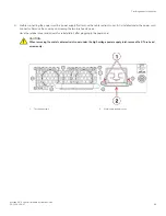
2. Ground the chassis by attaching a ground wire from building ground to an appropriate crimp connector and attaching the
connector to the 2AWG Panduit LCD2-14AF lug located to the left of the bottom fan assembly near the bottom of the chassis.
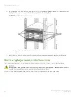
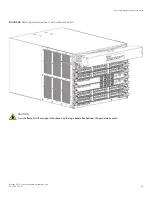
3. Remove the logo bezel protective cover if it is still installed over the top air vents on the port side of the chassis. Refer to
Removing logo bezel protective cover
on page 62 for instructions.
CAUTION
Remove the logo bezel protective cover on the port side of chassis before applying power. This cover is attached
over the air vents. If not removed, the chassis can overheat and will eventually shut down.
4. Install all power supplies provided for your device if not already installed. Refer to
on page 187 for
procedures.
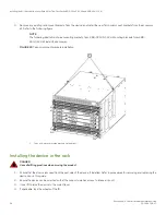
5. When installing the device in a rack, route power cables from power distribution units (PDUs) so they do not cover air vents in
chassis.
Providing power to the device
Brocade X6-4 Director Hardware Installation Guide
68
53-1004106-07
Содержание X6-4
Страница 12: ...Brocade X6 4 Director Hardware Installation Guide 12 53 1004106 07...
Страница 20: ...Brocade X6 4 Director Hardware Installation Guide 20 53 1004106 07...
Страница 28: ...Brocade X6 4 Director Hardware Installation Guide 28 53 1004106 07...
Страница 64: ...Brocade X6 4 Director Hardware Installation Guide 64 53 1004106 07...
Страница 86: ...Brocade X6 4 Director Hardware Installation Guide 86 53 1004106 07...
Страница 102: ...Brocade X6 4 Director Hardware Installation Guide 102 53 1004106 07...
Страница 130: ...Brocade X6 4 Director Hardware Installation Guide 130 53 1004106 07...
Страница 140: ...Brocade X6 4 Director Hardware Installation Guide 140 53 1004106 07...
Страница 166: ...Brocade X6 4 Director Hardware Installation Guide 166 53 1004106 07...
Страница 196: ...Brocade X6 4 Director Hardware Installation Guide 196 53 1004106 07...
Страница 200: ...Brocade X6 4 Director Hardware Installation Guide 200 53 1004106 07...
Страница 204: ...Brocade X6 4 Director Hardware Installation Guide 204 53 1004106 07...
Страница 210: ...Brocade X6 4 Director Hardware Installation Guide 210 53 1004106 07...
Страница 224: ...Brocade X6 4 Director Hardware Installation Guide 224 53 1004106 07...
Страница 238: ...Brocade X6 4 Director Hardware Installation Guide 238 53 1004106 07...