


12. After power is applied, the power supply LED will light green.
The director performs a power-on self-test (POST) each time it is powered on. POST takes approximately 10 minutes, during
which time status LEDs on installed blades and other FRUs may display amber. Power LEDs on all FRUs display green when
power-on self-test (POST) is complete and all FRUs are functional. You can bypass POST by using the
fastBoot
command.
You can also disable POST for successive reboots on the device using the
diagDisablePost
command.
NOTE
Do not connect the device to the network until the IP addresses are
configured.
13. After POST is complete, verify that the power LEDs on blades and other FRUs are green.
For information about LED patterns, refer to
Monitoring the Device
.
14. Ground the chassis by attaching a ground wire from facilites ground to an appropriate crimp connector and attaching the
connector to the 2AWG Panduit LCD2-14AF lug located to the left of the bottom fan assembly near the bottom of the chassis.
Using HVAC/HVDC power cords
HVAC/HVDC power supply power cords, available from Brocade, are shipped with an Anderson Saf-D-Grid
®
400 connector on the
power supply end and three unterminated 14 AWG UL 600V 90C wires with ring lugs on the power source end. Power cord length is 6
m (19 ft. 8 in.). For connecting to a power source, attach either an AC power plug to these wires that meets your facility and local code
requirements, or connect these wires to appropriate DC power terminal blocks.
The following table defines the function of the 14 AWG wires in the power cable:
TABLE 13
HVAC/HVDC power cable
Wire label
Color
Function
L+
Brown
Return positive (+)
–
Blue
Negative (-)
PE
Green with yellow stripe
Earth ground (PE)
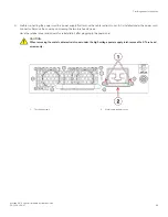
The Anderson Saf-D-Grid
®
connector on the power supply end of the cord is keyed so that it only fits one way into the power supply.
Note that the connector's latch should be positioned under the connector and will latch when the power cord connector is fully inserted
into the power supply.
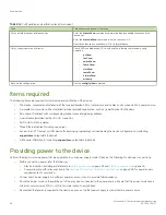
Providing power to the device
Brocade X6-4 Director Hardware Installation Guide
72
53-1004106-07
Содержание X6-4
Страница 12: ...Brocade X6 4 Director Hardware Installation Guide 12 53 1004106 07...
Страница 20: ...Brocade X6 4 Director Hardware Installation Guide 20 53 1004106 07...
Страница 28: ...Brocade X6 4 Director Hardware Installation Guide 28 53 1004106 07...
Страница 64: ...Brocade X6 4 Director Hardware Installation Guide 64 53 1004106 07...
Страница 86: ...Brocade X6 4 Director Hardware Installation Guide 86 53 1004106 07...
Страница 102: ...Brocade X6 4 Director Hardware Installation Guide 102 53 1004106 07...
Страница 130: ...Brocade X6 4 Director Hardware Installation Guide 130 53 1004106 07...
Страница 140: ...Brocade X6 4 Director Hardware Installation Guide 140 53 1004106 07...
Страница 166: ...Brocade X6 4 Director Hardware Installation Guide 166 53 1004106 07...
Страница 196: ...Brocade X6 4 Director Hardware Installation Guide 196 53 1004106 07...
Страница 200: ...Brocade X6 4 Director Hardware Installation Guide 200 53 1004106 07...
Страница 204: ...Brocade X6 4 Director Hardware Installation Guide 204 53 1004106 07...
Страница 210: ...Brocade X6 4 Director Hardware Installation Guide 210 53 1004106 07...
Страница 224: ...Brocade X6 4 Director Hardware Installation Guide 224 53 1004106 07...
Страница 238: ...Brocade X6 4 Director Hardware Installation Guide 238 53 1004106 07...