CHAPTER 3
-
Main Functions and Operation of the Machine
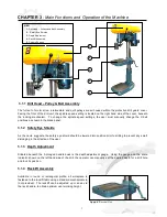
3.1.1 Drill Head – Pulley & Belt Assembly
The full set of motor drive, intermediate and quill pulleys are all housed within the protective drill guard cover.
Facing the front of the drill unit, the spindle speed setting is located on the right hand side of the cover, beneath
the locking mechanism. To change the spindle speed settings, the user must manually change the V-belt
positions as shown in the black panel.
3.1.2 Safety Eye Shields
As the name suggests, the safety eye shield should be lowered into position prior to drilling to prevent any swarf
dislodging in the direction of the user.
3.1.3 Depth Adjustment
Situated beneath the 3-pronged handle boss is the depth adjustment gauge. Using the gauge and the scale
indicator shown on the left hand side of the drill, the operator can manually set the desired depth for a drill hole
and lock its position.
3.1.4 Racklift Assembly
Available in round or rectangular profile, all workpiece is
fastened to the racklift table using a standard mechanical vie
(not provided). The racklift can be adjusted up or down via
the rack handle, to obtain optimum user working height.
2
4
5
KEY:
1.
Drill Head – Pulleys and Belt Assembly
2.
Safety Eye Shields
3.
Depth Adjustment
4.
Racklift Assembly
5.
Column Support
7
1
3
Figure 4.
Electrical Unit
Содержание 3M
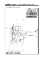
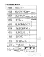
Страница 12: ...CHAPTER 4 Drawings Layouts Assembly and Spare Parts 4 1 1 Assembly Drawing Sheet 1 of 5 9 ...
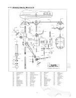
Страница 13: ...4 1 2 Assembly Drawing Sheet 2 of 5 10 ...
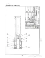
Страница 14: ...4 1 3 Assembly Drawing Sheet 3 of 5 11 ...
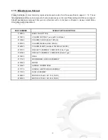
Страница 15: ...4 1 4 Assembly Drawing Sheet 4 of 5 12 ...
Страница 17: ...4 2 Switch Assembly 14 ...

