background image

281 Issue 1 - Service Manual - BX3  

37 


Installation is a reversal of the removal procedure with attention to the following points: 

  Clean both surfaces to be re-mated together. 

  Ensure  all  wiring  connections  are  positively  located  and  that  no  looms  have  been 

damaged. 

  When re-inserting the burner assembly, ensure that the injectors are inserted into the ring 

on the top of the burners correctly. 

  Ensure that the gas inlet feed-tube is retightened and checked for leaks. 

  Ensure that the gas valve loom is not damaged along its length and at the connector. 


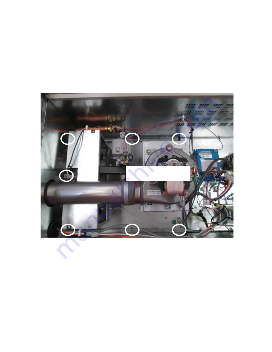
Heat exchanger removal (Photos) 


Screw locations (7 off) 
securing heat exchanger. 

Содержание BX3 Series

Страница 1: ... Manual BX3 Buffalo Gas Ducted Heater Service shall be carried out only by Authorised Personnel This Service Manual must NOT be left with the Owner or distributed to other persons not permitted to obtain this information by Brivis Climate Systems ...

Страница 2: ... forced The model range as follows Model KiloWatt Star Rating BX315 15 3 9 BX320 20 3 8 BX326 26 3 5 The New Brivis Buffalo BX3 Gas ducted heater consists of the following features The Tytronics HCDSI24 1DT Gas Fired ducted Heater control board with LED diagnostic display A direct main burner ignition system Single speed fan forced combustion process Supply air and flame roll out over temperature ...

Страница 3: ...ing Dismantling Procedures Further information on installation and operation of Brivis Buffalo BX3 heaters can be obtained from the Heating Installer s Manual and Heating Owner s manual Note Safety Warning DO NOT PLACE ARTICLES ON OR AGAINST THIS APPLIANCE DO NOT USE OR STORE FLAMMABLE MATERIALS NEAR THIS APPLIANCE DO NOT SPRAY AEROSOLS IN THE VICINITY OF THIS APPLIANCE WHILE IT IS IN OPERATION DO...

Страница 4: ...ion 10 3 3 Spark Igniter 11 3 4 Flame Sensor 11 3 5 Combustion Fan Operation 11 3 6 Burner 12 3 7 HCDSI24 1 Control Board 12 3 8 Pressure Switch 13 3 9 Main Fan Assembly Operation 13 3 10 Operation Flow Charts 14 3 11 Heater Shut down Flow Chart 15 4 0 INSTALLATION COMMISSIONING 16 5 0 TROUBLESHOOTING 16 5 1 LED Flash Codes 16 5 2 One Flash Over Heat Condition 18 5 3 Two Flashes Pressure Switch In...

Страница 5: ...OMPONENTS SERVICING 25 6 1 Gas Valve Servicing 25 6 2 Combustion Fan Servicing 27 6 3 Spark Igniter Servicing 28 6 4 Flame Sensor Servicing 28 6 5 Pressure Switch Servicing 29 6 6 Main Fan Assembly Servicing 29 6 7 Unit Operation 30 7 0 DISMANTLING PROCEDURES 31 7 1 Burner Assembly Removal 31 7 2 Gas Manifold Assembly Removal 31 7 3 Gas Valve Removal 32 7 4 Pressure Switch Assembly Removal 32 7 5 ...

Страница 6: ...le The HCDSI24 1 initiates an ignition cycle upon receiving a call for heat from an external thermostat The following will occur The micro controller shall check that the external flame safety guard is operational As the flame circuit is earth referenced additional checks are made to detect an earth disconnect The control board will do a safety check and make sure the pressure switch circuit is op...

Страница 7: ...281 Issue 1 Service Manual BX3 2 1 2 Circuit Diagram Brivis Buffalo BX3 ...

Страница 8: ...lour 1 Gas Valve Violet 2 Gas Valve Grey 3 Pressure Switch Yellow 4 W White 5 Hi Limit Black 6 24Vac Hi Limit Orange 7 24Vac Red 8 Ground Green High Voltage From left to right refer to diagram in section 1 1 Pin Function Colour 1 Flame Sense White 2 Neutral Blue 3 Combustion Fan Brown 4 Circulation Fan Red 5 Active Brown Wiring Colour ...

Страница 9: ...r 0 24m2 Airflow Total Static Pressure 50 Pa 75 Pa 100 Pa 125 Pa Standard 620l s 590l s 560l s 530l s Gas Valves VR8215S T Honeywell Main Burner In shot Burner Ignition System Tytronics HCDSI24 1DT control box Intermittent Sparking Pilot Heat Exchanger Aluminised Steel Tubes Control Fuse 2 Amp type 3AG Slow blow Transformer Model B024702 240 24 12V 50HZ 1 75Amps Over Temperature Switch Supply Air ...

Страница 10: ...m2 0 26 Airflow Total Static Pressure 50 Pa 75 Pa 100 Pa 125 Pa Standard 640l s 615l s 585l s 560l s XAir 685 655 630 600 Gas Valves VR8215S T Honeywell Main Burner In shot Burner Ignition System Tytronics HCDSI24 1DT control box Intermittent Sparking Pilot Heat Exchanger Aluminised Steel Tubes Control Fuse 2 Amp type 3AG Slow Blow Transformer Model T B024702 240 24 12V 50HZ 1 75Amps Over Temperat...

Страница 11: ...er 0 28 m2 0 29 Airflow Total Static Pressure 50 Pa 75 Pa 100 Pa 125 Pa Standard 805l s 780l s 760l s 740l s XA 825 805 785 765 Gas Valves VR8215S T Honeywell Main Burner Inshot Burner Ignition System Tytronics HCDSI24 1DT control box Intermittent Sparking Pilot Heat Exchanger Aluminised Steel Tubes Control Fuse 2 Amp type 3AG Slow blow Transformer Model T B024702 240 24 12V 50HZ 1 75Amps Over Tem...

Страница 12: ...082 17 Power 240Volts 240Volts 240Volts Maximum Current 1 8 Amp 2 5 Amp 4 4 Amp Capacitor 6 µF 10 µF 25 µF High Winding Resistance 20 C 20 6 Ohms 11 Ohms 6 9 Ohms Medium Winding Resistance 20 C 26 1 Ohms 14 6 Ohms 8 Ohms Low Winding Resistance 20 C 31 6 Ohms 18 Ohms 9 3 Ohms Impellor Size diam x width 255mm x 180 mm 255mm x 180 mm 284mm x 265 mm ...

Страница 13: ...Remove thermostat backing plate from the front cover and mount on the wall Draw wires from the wall cavity connect R W terminals on the heater Terminal Block to the R W terminals on the thermostat refer Diagram 4 Insert batteries and mount thermostat front cover onto the backing plate For more information refer to the Installation Guide and Operating Manual supplied with the Brivis Manual or Progr...

Страница 14: ...lay NC 24Vac coil switching 240Vac Y 5 Heater Control Board N 6 CDU Compressor Relay Y 7 Sheathed conductor wire minimum 0 75mm cross sectional area Y 8 Sheathed conductor wire minimum 0 75mm cross sectional area Y 9 Terminal block on Heater N 10 Brivis Programmable Controller Purchase from Brivis Table 2 Supplied Field supplied components for Add On connection Notes 1 All electrical works to comp...

Страница 15: ...natural gas it has been optimised for direct ignition application and includes a on and off switch and a pressure regulator The gas valve is controlled by the HCDSI 24 1 PCB control Please see the technical data sheet for the optimum gas pressures Pressure switch Control Board Transformer Thermostat connection Main Circulation fan compartment Combustion Fan Gas Valve Flame roll out plate Flame rol...

Страница 16: ...t be drawn into the heat exchanger Fortunately there are measuring devices to prevent these occurrences from causing an unsafe condition The combustion fan operates at a fixed fan speed and is switched on and off by the HCDSI 24 1 control When the fan is in operation the suction effect of the fan creates a vacuum inside the heat exchanger from the heat exchanger inlet ports all the way through to ...

Страница 17: ...rom the suction force developed from the combustion fan There is a cross lighting gallery near the burner exit which allows for cross ignition between each adjacent burner 3 7 HCDSI24 1 Control Board The HCDSI24 1 control is a single printed circuit board PCB assembly mounted within a plastic enclosure The controller provides status and diagnostic information directly through the use of a Green LE...

Страница 18: ...ox If there is insufficient vacuum pressure to ensure safe and reliable ignition or combustion quality the switch will go open circuit and the 24 volt supply to the gas valve cut 3 9 Main Fan Assembly Operation ROOM AIR FAN A centrifugal fan and Permanent Split Capacitor PSC motor housed in a metal scroll are used for room air circulation and this is contained within the fan cabinet The room fan h...

Страница 19: ...iate main fan hold off time of 20 seconds Fan speed ramps up to required speed Steady state operation Flame detect time Has flame been detected within 5 seconds Ignition retry phase activated 5 Max number of Ignition attempts No No Flame validate time Has flame been present for 5 5 seconds Yes Pressure Switch Closes Normal operation continues System checks Flame sensors earth Pressure switch open ...

Страница 20: ...281 Issue 1 Service Manual BX3 15 3 11 Heater Shut down Flow Chart Gas valve closes Heater thermostat switched off Combustion fan post purge 5 sec Circulation Fan Off Delay 80 Seconds Main fan turns off ...

Страница 21: ...mS flashcode Pressure Switch inactive Fan running but pressure switch 101000000000000000000000 is still open Fan stopped but pressure switch is still closed Three flash 200mS flashcode Purge Interwait 101010000000000000000000 Timer operating eg Stat off during flame Establishment time Flame establishment time elapsed without flame Four flash 200mS flashcode Pressure Switch Lockout Pressure Switch ...

Страница 22: ...me sense fault 200mS flashcode Flame variation detected due to poor earth connection to 1111100111100111100000000 chassis ground A lockout is a result of a detected fault condition caused by an operational or a safeguard fault In the case of a lockout the unit shall both de energise the triac drive and stop the control signal to the relay drive circuit Consequently the gas valve is completely isol...

Страница 23: ... cleared and the switch resets i e switch closes within a specific time a cool down period will operate for a duration of 120sec Then the normal heating cycle can commence again provided the wall control is still calling for heat Service Check List Check the temperature rise value of the supply air thermistor and nearest outlet temperature over the room temperature Return air intake temperature A ...

Страница 24: ... seconds the 2 flash fault code is displayed If the pressure switch remains open longer than 4 minutes the unit shall lockout and the four flash fault code is flashed on the status LED once lockout occurs the combustion fan turns off Service Check List Vacuum Pressure Checking Procedure Measure vacuum pressure at the pressure switch during pre purge or force an overheat condition by breaking the o...

Страница 25: ...ns open longer than 4 minutes the unit shall lockout Once lockout occurs the combustion fan turns off Service Check List 1 Refer to Check List for 2 flash Pressure switch inactive 5 6 Five Flashes Ignition Lockout Reason Ignition lockout failure to Ignite flame within the maximum allowable Ignition retry phase There is a maximum of 5 re ignition attempts before the control board will lockout If a ...

Страница 26: ...ctivation continues longer than overheat fan and cool down Service Check List Please refer to overheat conditions in this manual 5 9 Eight Flashes Frequency Lockout Reason Supply frequency outside operating limits Microprocessor clock outside operating limits The frequency check determines that the operating frequency of the micro controller internal clock is correct Comparison against the known m...

Страница 27: ...kout Service Checklist 1 Check power supply 2 Check polarity at power point 3 Check transformer voltage 4 Check over heat switch is faulty 5 Gas valve passing gas 5 12 Eleven Flashes SafeStart Lockout Reason Main valve safeguard too slow or failed to activate hardware fault Confirmation that the secondary safeguard hardware timing circuit is within tolerance Measurements are made by the micro cont...

Страница 28: ...ondition has been cleared Service Checklist 1 Check the earthing system 2 Check the control board 3 Check the flame sensor 4 Check the gas valve 5 Check the flame roll out switch 6 Check the flame roll out switch loom 5 15 Three Slow Flashes Ground Fault Lockout Reason Flame variation detected due to poor earth connection to chassis ground There has been a false flame that is detected during a pow...

Страница 29: ...re has been a false flame that is detected during a power reset turning on and off There has been a false flame has gone away after an over heat condition has been cleared Service Checklist 1 Check the earthing system 2 Check the control board 3 Check the flame sensor 4 Check the gas valve 5 Check the flame roll out switch 6 Check the flame roll out switch loom ...

Страница 30: ...cking and adjustment only if required To check for correct gas valve settings and operation the following should be performed and adjustments made when necessary Inlet Pressure Measurement Remove the gas inlet tap and replace with a pressure test point Connect a suitable manometer to the test point Turn on the heater and wait for the flame proving period to finish Check that the inlet gas pressure...

Страница 31: ...period to finish 3 Check the burner gas pressure and if it requires adjusting please follow the below steps 4 Unscrew the pressure regulator adjustment cap 5 There is a adjustment screw under the cap which will adjust the burner pressure 6 Clockwise will increase the gas pressure 7 Anticlockwise will decrease the gas pressure 8 The table below shows the gas pressure for each unit 9 Turn the unit o...

Страница 32: ...tion fan 5 Re apply power to the heater and force it into an overheat mode to power up the combustion fan Warning Remember the motor operates with 240 Vac 6 Measure the combustion fan vacuum pressure and ensure that it reaches the value as specified in the table below Combustion Fan Motor Resistance Reading Fime Winding Resistance 20oC 24 3 Ohms If the vacuum pressure is below the specified values...

Страница 33: ...ation relative to burner face 1 Remove the burner assembly as described in removal procedure 5 2 Measure the distances as shown in the diagram below 3 Installation is a reversal of the removal procedure 6 4 Flame Sensor Servicing Isolate the heater power and gas supply from the unit Checking the flame sensor 1 Check that the flame sensor rod is clean located correctly and the lead and plug connect...

Страница 34: ...nsation 6 Check the hoses leading to the pressure switch are clear of foreign material 7 Reassemble Unit Pressure switch Opens BX315 115pa BX320 80pa BX326 50pa 6 6 Main Fan Assembly Servicing Internal Models 1 Turn the unit OFF and isolate the power supply 2 Remove the panel on the fan compartment gas entry side of the heating unit so there is access to the fan motor assembly 3 Remove fan housing...

Страница 35: ...do not leak 3 Check the wall control wiring connection at the unit is in good condition 4 Check the maximum burner pressure at the test point provided on the gas valve 5 Check the duct system airflow distribution balance and adjust as required 6 Check the unit s selected 3 speed fan is appropriate for optimum heat output for the application ...

Страница 36: ... 8 The burner assembly can now be removed Installation is a reversal of the removal procedure with attention to the following points 1 Ensure that the gas inlet feed tube is retightened and checked for leaks 2 Ensure that all looms wires and leads are not damaged along their length and at the connectors 7 2 Gas Manifold Assembly Removal 1 Turn the gas isolation valve off and isolate the heater s p...

Страница 37: ...l 1 Isolate the heater s power supply 2 Remove the hose from the pressure switch 3 Remove the electrical wires from the pressure switch 4 Remove the pressure switch fastening screw if the pressure switch is to be replaced Installation is a reversal of the removal procedure with attention to the following points Ensure all wiring connections are positively located and that no looms have been damage...

Страница 38: ... onto the combustion fan outlet 5 Remove the flue pipe and rubber silicone connector 6 Remove 3 screws which fasten the combustion fan down to the combustion fan box 7 Pry the combustion fan off the box which will still be fastened by the sealing heat proof silicon Installation is a reversal of the removal procedure with attention to the following points 1 Clean both surfaces to be re mated togeth...

Страница 39: ... looms are not restricting the removal of the plate until you expose the fan motor assembly 6 Slide the fan motor upwards and away from the fan compartment 7 Remove fan motor plate from the fan scroll See below for Motor and play removal Installation is a reversal of the removal procedure Removal of the fan assembly Unscrew the screws holding the top plate down and then remove carry handle Remove ...

Страница 40: ...e PCB assembly 4 Remove the 4 screws that secure the HCDSI 24 1 to the top plate of the fan compartment WARNING Care should be taken to prevent any damage to the wiring and PCB Installation is a reversal of the removal procedure with attention to the following points Ensure all wiring connections are positively located and that no looms have been damaged 7 8 240 to 24 Volt Transformer Removal 1 Is...

Страница 41: ...e out of the unit 5 Remove the burner manifold 6 Remove the pressure switch hose 7 Remove the burner assembly 8 Remove the 8 screws that hold the heat exchanger to the frame of the unit 9 Remove the 2 screws that hold the side panel flue end on the external part of the unit and pull away from the unit This will expose the entire gas feed pipe 10 Unscrew the gas feed tube off the gas cock and then ...

Страница 42: ...ively located and that no looms have been damaged When re inserting the burner assembly ensure that the injectors are inserted into the ring on the top of the burners correctly Ensure that the gas inlet feed tube is retightened and checked for leaks Ensure that the gas valve loom is not damaged along its length and at the connector Heat exchanger removal Photos Screw locations 7 off securing heat ...

Страница 43: ...dingly this guide must be read in conjunction with and subject to all laws regulations and industry standards applicable in the State or Territory in which the products are installed You must ensure that the installation of the products will comply with those laws regulations and standards and that the products recommended to customers are fit for the purpose for which they are intended ...

Страница 44: ...S 1300 274 847 Fax 61 03 9264 9400 www brivis com au email sales brivis com au Brivis New Zealand Distributor Warm Air Ltd 69 Marsden Street Lower Hutt 5010 New Zealand PO Box 38523 Wellington Mail Centre Wellington 5043 New Zealand 0800 WARMAIR 0800 9276 247 Ph 64 04 920 1670 Fax 64 04 920 1681 www warmair co nz email sales warmair co nz Brivis South Africa Distributor Lorenz and Associates North...

Отзывы: