5
117
13
Installation
1. Lightly lubricate fuel injector O-rings with clean
engine oil.
2. Install fuel injectors into intake manifold.
3. Install retaining clips to secure fuel injector caps to
fuel injectors. Orient retaining clips as noted during
removal. Be sure retaining clips are fully engaged.
4. Install two hex flange screws to fasten fuel injector
cap flanges to intake manifold. Tighten screws to
50-60 lb-in
(6-7 Nm).
5. Connect fuel injector connectors. Push in green
secondary locks to secure.
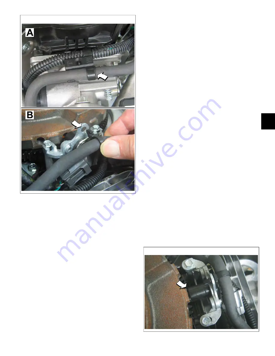
6. Install EFI wire harness retaining clip onto fuel rail.
7. Install fuel rail retaining clip onto fuel rail. Install fuel
rail retaining clip into hole in CKP sensor bracket.
8. Route quick disconnect fitting on fuel rail through
opening in cylinder 2 heat shield to fuel pump
module.
9. Firmly push quick disconnect fitting onto fuel pump
module. Gently tug on fitting to verify that it is properly
seated and secure.
10. Turn ignition switch ON for two seconds, and then
OFF for 10 seconds. Turn the ignition switch back to
ON and check for fuel leaks.
11. See
Air Cleaner Assembly/Static Guard/Decorative
Cover/Blower Housing, Installation
.
CKP Sensor
Removal
1. See
Air Cleaner Assembly/Static Guard/Decorative
Cover/Blower Housing, Removal
.
2. Remove fuel rail retaining clip from hole in CKP
sensor bracket.
3. Remove two hex flange screws to release CKP
sensor bracket from cylinder mounting bosses.
4. Disconnect CKP sensor connector.
Installation
1. Start two hex flange screws to fasten CKP sensor
bracket to cylinder mounting bosses. Alternately
tighten screws until snug.
2. On side opposite connector, install mounting plate in
groove of CKP sensor housing.
3. Insert CKP sensor into bracket. Align hole in
mounting plate with hole stamped “49” on bracket.
Install TORX screw and tighten to
25-35 lb-in
(3-4
Nm).
4. Loosen two bracket screws and adjust as necessary
until gap between CKP sensor and flywheel tooth is
0.010 inches
5. Alternately tighten CKP sensor bracket screws to
20-30 lb-in
(2-3 Nm).
6. Connect CKP sensor connector.
14
Not for
Reproduction
Содержание VANGUARD M490000
Страница 2: ...N o t f o r R e p r o d u c t i o n ...
Страница 6: ...N o t f o r R e p r o d u c t i o n ...
Страница 84: ...3 80 MODEL 490000 EFI ELECTRICAL SCHEMATIC PAGE 1 OF 2 N o t f o r R e p r o d u c t i o n ...
Страница 85: ...3 81 MODEL 490000 EFI ELECTRICAL SCHEMATIC PAGE 2 OF 2 N o t f o r R e p r o d u c t i o n ...
Страница 88: ...3 84 MODELS 540000 610000 TURF EFI ELECTRICAL SCHEMATIC PAGE 1 OF 2 N o t f o r R e p r o d u c t i o n ...
Страница 89: ...3 85 MODELS 540000 610000 TURF EFI ELECTRICAL SCHEMATIC PAGE 2 OF 2 N o t f o r R e p r o d u c t i o n ...
Страница 92: ...3 88 MODEL 610000 MARINE EFI ELECTRICAL SCHEMATIC PAGE 1 OF 2 N o t f o r R e p r o d u c t i o n ...
Страница 93: ...3 89 MODEL 610000 MARINE EFI ELECTRICAL SCHEMATIC PAGE 2 OF 2 N o t f o r R e p r o d u c t i o n ...
Страница 95: ...3 91 MODELS 490000 540000 610000 FUSE RELAY BLOCK N o t f o r R e p r o d u c t i o n ...
Страница 96: ...3 92 N o t f o r R e p r o d u c t i o n ...
Страница 110: ...4 106 N o t f o r R e p r o d u c t i o n ...
Страница 115: ...5 111 This page is intentionally left blank N o t f o r R e p r o d u c t i o n ...
Страница 126: ...5 122 20 NOTE Access cover and blower housing removed for illustration purposes N o t f o r R e p r o d u c t i o n ...
Страница 134: ...5 130 30 N o t f o r R e p r o d u c t i o n ...
Страница 137: ...5 133 This page is intentionally left blank N o t f o r R e p r o d u c t i o n ...
Страница 138: ...5 134 32 N o t f o r R e p r o d u c t i o n ...
Страница 140: ...5 136 33 N o t f o r R e p r o d u c t i o n ...
Страница 142: ...5 138 This page is intentionally left blank N o t f o r R e p r o d u c t i o n ...
Страница 143: ...N o t f o r R e p r o d u c t i o n ...


