Siemens SIMOTICS DP series, Operating Instructions Manual
The Siemens SIMOTICS DP series is a high-performance industrial drive system for various applications. Enhance your productivity with this efficient solution by accessing the Operating Instructions Manual, available for free download on our website. Obtain detailed instructions and optimize your operations at manualshive.com.
Share
Download


Reviews:
No comments
Related manuals for SIMOTICS DP series

MGV Series
Brand: Parker Pages: 39

KD45V20
Brand: Kohler Pages: 108

L48V
Brand: Yanmar Pages: 38
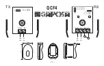
QCF4
Brand: GAPOSA Pages: 20

MOTOR99
Brand: Kuda Pages: 98

StarDental Titan-E
Brand: DentalEZ Pages: 2

DHG6015NUC
Brand: Bosch Pages: 20

Rexroth Hagglunds CA 10
Brand: Bosch Pages: 53

MKE098
Brand: Bosch Pages: 60

Rexroth MKE
Brand: Bosch Pages: 74

Rexroth Hagglunds CA 100
Brand: Bosch Pages: 76

Rexroth 70 Series
Brand: Bosch Pages: 56

Rexroth IndraDyn T
Brand: Bosch Pages: 76

Rexroth A10VER 52 Series
Brand: Bosch Pages: 56

HBL 44 Series
Brand: Bosch Pages: 48

Rexroth MAD
Brand: Bosch Pages: 114

Rexroth MAD100
Brand: Bosch Pages: 72

Rexroth A6VM series 71
Brand: Bosch Pages: 76


