


Not for
Reproduction
16
NOTICE
Refer to your engine owner's manual for specific fuel
recommendations.
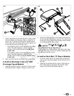
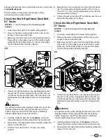
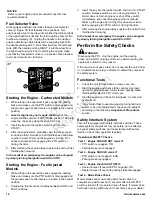
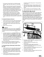
Fuel Selector Valve
Units equipped with two fuel tanks feature a fuel selector
valve (A, Figure 37) that features three positions. Two
positions allow fuel to be drawn from either the left-hand tank
or the right-hand tank (B) and the third position shuts off the
fuel flow completely (C). Turning the handle to the desired
position determines which tank will be supplying fuel. With
the handle pointing LEFT, it will draw fuel from the left-hand
tank. With the handle pointing RIGHT, it will draw fuel from
the right-hand fuel tank. Prior to starting the engine, make
sure that the fuel selector valve is in a position that will allow
fuel to be drawn from a fuel tank.
37
Starting the Engine - Carbureted Models
1. While sitting in the operator's seat, engage the parking
brake and make sure the PTO switch is disengaged and
the ground speed control levers are locked in the neutral
position.
2.
A warm engine may not require choking.
Set the
engine throttle control to FAST throttle position. Then fully
close the choke by pulling the knob OUT fully.
3. Insert the key into the ignition switch and turn it to
START.
4. After the engine starts, gradually open the choke (push
knob down fully). Reduce to half throttle speed and allow
engine to warm.
Warm up the engine by running it for
atleast a minute before engaging the PTO switch or
driving the rider.
5. After warming the engine always operate the unit at FULL
throttle when mowing.
In the event of an emergency the engine can be stopped
by simply turning the ignition switch to STOP.
Starting the Engine - Fuel Injected
Models
1. While sitting in the operator's seat, engage the parking
brake and make sure the PTO switch is disengaged and
the ground speed control levers are locked in the neutral
position.
2. Position the throttle control midway between SLOW and
FAST positions.
3. Insert the key into the ignition switch and turn it to START
position. Release switch as soon as engine starts. If
starter does not turn engine over, shut off key switch
immediately, and consult engine operator's manual.
Warm up the engine by running it for at least a minute
before engaging the PTO switch or driving the rider.
4. After warming the engine always operate the unit at FULL
throttle when mowing.
In the event of an emergency the engine can be stopped
by simply turning the ignition switch to STOP.
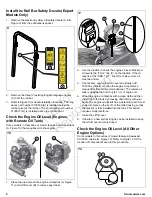
Perform the Safety Checks
WARNING
Disengage the PTO, stop the engine, set the parking
brake, and wait for moving parts to stop before leaving the
operator’s position for any reason.
If the unit does not pass a test, do not operate the unit. Under
no circumstance should you attempt to defeat the purpose of
the safety system.
Functional Tests
1. Check the unit for loose bolts, screws, nuts, etc.
2. Start the engine and check all the controls for proper
operation: ground speed control levers, parking brake,
throttle cable, electric PTO clutch, etc.
3. Stop the engine and check for fluid leaks: oil, fuel, and
hydraulic oil.
4. If any control fails to operate properly during testing or
seems to be out of adjustment, check and re-adjust it
according to the following
Adjustment Procedures
section.
Safety Interlock System
This unit is equipped with safety interlock switches. These
safety systems are present for your safety, do not attempt
to bypass safety switches, and never tamper with safety
devices. Check their operation regularly.
Operational SAFETY Checks
Test 1 - Engine SHOULD NOT crank if:
• PTO switch is engaged, OR
• Parking brake is not engaged.
Test 2 - Engine SHOULD crank if:
• PTO switch is not engaged, AND
• Parking brake is engaged.
Test 3 - Engine should SHUT OFF if:
• Operator rises off seat with PTO engaged, OR
• Operator rises off seat with parking brake disengaged.
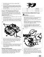
Test 4 - Blade Brake Check
Mower blades and mower drive belt should come to a
complete stop within seven (7) seconds after electric PTO
switch is turned off (or operator rises off seat). If mower drive
belt does not stop within seven (7) seconds, see your dealer.
Содержание IS3200Z Series
Страница 1: ...N o t f o r R e p r o d u c t i o n ...
Страница 23: ...N o t f o r R e p r o d u c t i o n Notes ...
Страница 24: ...N o t f o r R e p r o d u c t i o n ...


