background image

Not for 

Reproduction

15

32

33

34

Lubricate the Front Casters


Interval:

 Annually 

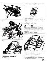
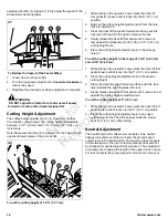
1. Remove the 1/4-28 bolt (A, Figure 35) screwed into the

caster and install a 1/4-28 grease fitting. 

35

2. Grease the front caster. 
3. Remove the 1/4-28 grease fitting and reinstall the 1/4-28

bolt. 

4. Repeat the process for the other side of the machine. 

Checking / Adding Fuel

 WARNING 

Gasoline is highly flammable and must be handled with

care. Allow engine to cool for at least 3 minutes before

refueling. Do not allow open flame, smoking or matches in

the area. Avoid over-filling and wipe up any spills. 


To add fuel: 


1. Remove the fuel cap (A, Figure 36). 

36

2. Fill the fuel tank to the bottom of the filler neck. This will

allow for fuel expansion. 

Note: Do not overfill. Refer to your engine owner's

manual for specific fuel recommendations. 

3. Install and hand tighten the fuel cap. 
4. If your unit is equipped with two fuel tanks, repeat this

process to fill the other fuel tank. 

Содержание IS3200Z Series

Страница 1: ...N o t f o r R e p r o d u c t i o n ...

Страница 2: ...er Decks Install the discharge chute 72 Export Mower Decks Install the mower deck drive belt 72 Export Mower Decks Check the deck lift rod timing Check and level the mower deck Check the mower deck drive belt Lubricate all grease and oil points Check Add fuel Start the engine PERFORM THE SAFETY CHECKS Check for LOOSE HARDWARE Check all OPERATOR CONTROLS Perform SAFETY INTERLOCK SYSTEM CHECK Regist...

Страница 3: ...c actuator counter clockwise to the run position marked run on the transmission C Note Both hydraulic actuators must be in the same position Operating the Seat Latch Some models are equipped with a seat latch that secures the seat plate in place The seat latch is located by the left rear corner of the seat plate 1 To raise the seat plate release the latch by moving the seat latch A Figure 2 toward...

Страница 4: ...lign the handles with each other Install the Seat This procedure is only necessary if the seat is not factory installed on your unit Some models are equipped with two sets of holes in the seat plate that the seat can be installed in Use the forward set of holes to position the operator closer to the front of the machine and the rear set of holes to position the operator towards the rear of the mac...

Страница 5: ... Install the roll bar into the roll bar pockets The roll bar is installed so that the safety decals are on the left side of the machine as determined from the operator s position facing towards the front of the machine When the mark you made is even with the top of the roll bar pocket the holes are close to being lined up If necessary use a dead blow hammer and drift pin to assist in lining up the...

Страница 6: ...engine oil level Maximum oil level is the FULL line C on the dipstick If the oil level is at the ADD 1 QT line D or below more oil must be added 3 If necessary open the oil fill cover and slowly add 15W 50 synthetic oil See the engine oil operator s manual for other oil recommendations The remote oil tank is designed to hold 5 qt 4 73 L of engine oil 4 Wipe the engine oil dipstick with a clean clo...

Страница 7: ...s it may be necessary to purge air from the hydraulic system If the unit is not driving properly perform the Purging the Air from the Hydraulic System procedure Check Tire Pressures Tire pressure should be checked periodically and maintained at the levels shown in the chart Note that these pressures may differ slightly from the Max Inflation stamped on the side wall of the tires The pressures show...

Страница 8: ...ided 6 Secure the other end of the mount pin in place by installing a 3 8 16 X 1 bolt I and 390 X 1 50 X 109 washer J into the internal threads of the mount pin 7 Repeat the process to install the right hand pusher bar to the mower deck Install the Mower Deck 72 Export Models 1 Park the zero turn rider on a flat level surface Engage the parking brake turn the ignition switch to OFF and remove the ...

Страница 9: ...eck Install the Discharge Chute 72 Side Discharge Export Models 1 Install the discharge chute A Figure 19 onto the mower deck B as shown in Figure 19 using the pivot rod C 19 2 Secure the discharge chute to the mower deck using two 2 5 16 washers D and nylon nuts E The mower deck should never be run without the discharge chute installed and positioned in the down position WARNING Amputation and Th...

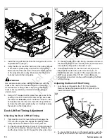
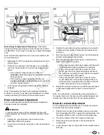
Страница 10: ...release the tension on the breaker bar Deck Lift Rod Timing Adjustment Checking the Deck Lift Rod Timing 1 Park machine on a flat level surface Disengage the PTO stop the engine and engage the parking brake Verify the tires are inflated to the correct pressure 2 To check the inner lift rod A Figure 21 timing measure and record the distance between the inner lift pivots B and the inner rod pivots C...

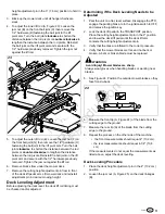
Страница 11: ...n desired mowing height Deck Leveling Adjustment Before adjusting the deck level the deck lift rod timing must be checked and or adjusted Determining if the Deck Leveling Needs to be Adjusted 1 Park the unit on a flat level surface Disengage the PTO engage the parking brake turn the ignition switch to OFF and remove the ignition key 2 Lock the deck lift pedal in the TRANSPORT position Place the cu...

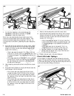
Страница 12: ...was being raised when it was unable to achieve the 4 10 2 cm in the front and 4 1 4 10 8 cm in the rear measurement position the hardware in the next lower hole B in the mower deck mount C If the mower deck was being lowered when it was unable to achieve the 4 10 2 cm in the front and 4 1 4 10 8 cm in the rear measurement position the hardware in the next higher hole in the mower deck mount 26 7 R...

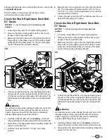
Страница 13: ... release the tension on the idler arm 7 Set the mower deck to the 3 1 2 8 9 cm cutting position 8 Measure the coil to coil length J of the idler arm spring K The measurement should equal 6 1 8 15 6 cm 1 8 0 32 cm If not turn the adjustment nut L until the measurement is achieved 9 Tighten the jam nut and the 3 8 nut that secures the rear back side idler pulley to the deck Check the Short Right Han...

Страница 14: ...rive idler arm I and rotate the idler arm clockwise which will relieve the tension on the belt exerted from the idler arm 3 Re seat the long left hand belt and carefully release the tension on the idler arm 4 Set the mower deck to the 3 1 2 8 9 cm cutting position 5 Measure the coil to coil length A Figure 31 of the long left hand belt tensioning spring B The measurement should equal 10 1 4 26 cm ...

Страница 15: ...ine is highly flammable and must be handled with care Allow engine to cool for at least 3 minutes before refueling Do not allow open flame smoking or matches in the area Avoid over filling and wipe up any spills To add fuel 1 Remove the fuel cap A Figure 36 36 2 Fill the fuel tank to the bottom of the filler neck This will allow for fuel expansion Note Do not overfill Refer to your engine owner s ...

Страница 16: ...FAST positions 3 Insert the key into the ignition switch and turn it to START position Release switch as soon as engine starts If starter does not turn engine over shut off key switch immediately and consult engine operator s manual Warm up the engine by running it for at least a minute before engaging the PTO switch or driving the rider 4 After warming the engine always operate the unit at FULL t...

Страница 17: ...ent Knob Suspension Ride Comfort The seat adjustment knob B adjusts the suspension of the seat ride comfort Turn the adjustment knob until the display scale has a reading that matches the weight of the operator Lumbar Adjustment Lever Turn the lumbar adjustment knob until the desired amount of lumbar is achieved Back Angle Adjustment Knob Turn the back angle adjustment knob until the desired amoun...

Страница 18: ...it comes to rest against the stationary pin E in the 1 1 2 3 37 cm cutting height hole 5 Place the cutting height adjustment pin in the storage hole F To set the cutting height in the range of 1 3 4 4 40 cm and 4 3 4 12 06 cm 1 While sitting in the operator s seat press the deck lift foot pedal forward until it locks into the 5 12 7 cm position 2 Place the cutting height adjustment pin in the desi...

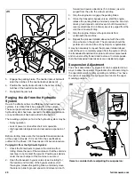
Страница 19: ...llar along the neutral return rod until it contacts and very lightly compresses the neutral return spring C 4 Move the ground speed control levers into the operating position pull rearward and release 5 Move the ground speed control levers out towards the NEUTRAL LOCKOUT position if the ground speed control lever aligns with the notch in the neutral lock plate adjustment is complete if the ground ...

Страница 20: ...ransaxle s bypass valves see Uncrating for the location and function of the bypass valves start the engine release the parking brake and slowly move the zero turn rider s ground speed control levers in both forward and reverse directions 5 to 6 times as air is purged from the unit the oil level will drop 3 Stop the engine and engage the parking brake 4 Close the transaxle s bypass valves start the...

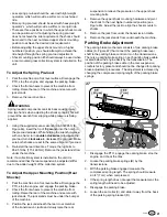
Страница 21: ...installed on the unit it is recommended that the rear suspension be adjusted stiffer due to the added weight of the collection system To Adjust the Upper Mounting Position Rear Shocks 1 Park the machine on a flat level surface Disengage the PTO stop the engine and engage the parking brake 2 Chock the front wheels to prevent the machine from rolling Raise the rear of the machine and secure with jac...

Страница 22: ...e brake mechanism 7 Turn the adjustment nut E to compress or release the spring 8 Engage the parking brake and re measure the spring Continue this process until the compressed spring length measures 2 3 4 7 cm 9 Position the set collar 3 8 0 96 cm away from the parking brake bracket and tighten If this does not correct the braking problem see your dealer ...

Страница 23: ...N o t f o r R e p r o d u c t i o n Notes ...

Страница 24: ...N o t f o r R e p r o d u c t i o n ...

Отзывы: