background image

10

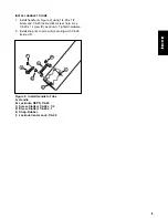
Figure 12. Install Cover Assembly
A. Bag Support Bracket
B. Cover Assembly
C. Cover Hinge Pins
D. Hair Pins
E. Hinge Pivots

D

INSTALL COVER ASSEMBLY

1. Attach cover assembly (B, Figure 12) to bag

support bracket (A) using hinge pivots (E). Secure
cover using cover hinge pins (C) and hair pins (D)
as shown.

C

E

A

B

C

D

E

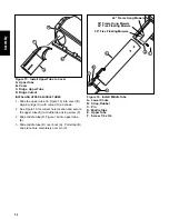
Figure 11. Attach Hitch and Upright Support
A. Hitch and Upright Support Assembly
B. Frame spacers

A

INSTALL HITCH AND UPRIGHT SUPPORT ASSEMBLY

1. Attach hitch and upright support assembly (A,

Figure 11) to frame spacers (B) as shown.

A

B

B

INSTALL BAG AND COVER SUPPORT

1. Install the bag and cover support (B, Figure 10) to

upright support (A) using reinforcement plate (C)
and 3/8-16 x 1 capscrews (D) and 3/8-16 locknuts
(E) as shown.

A

C

B

Figure 10. Install Bag and Cover Support
A. Upright Support 
B. Bag and cover Support
C. Reinforcement Plate
D. Capscrews, 3/8-16 x 1
E. Locknuts, 3/8-16

E

D

Assembly

Содержание 1695354

Страница 1: ...iption 1695354 44 50 Turboless Triple Catcher Turboless Triple Catcher Manual Part No 1734740 Revision 01 Rev Date 05 2007 TP 100 4527 01 AT SMAN C CA AU UT TI IO ON N R Re ea ad d a an nd d f fo ol ll lo ow w a al ll l i in ns st tr ru uc ct ti io on ns s ...

Страница 2: ...con Hazard Alert Read the Manual Thrown Objects Remove Key Before Servicing Machine Rollover Rotating Parts Do Not Touch Safety Icons The alert symbol is used to identify safety information about hazards that can result in personal injury A signal word DANGER WARNING or CAUTION is used with the alert symbol to indicate the likelyhood and the potential severity of the injury In addition a hazard ic...

Страница 3: ...cers Conquest 1700 2700 YT Prestige 1800 2800 GT Series 5 Remove Blowout Baffle 6 Install Baffles 7 Install Components 8 Install Bag and Cover Support 10 Install Hitch and Upright Support Assembly 10 Install Cover Assembly 10 Install Collector Bags 11 Install Lower Discharge Chute 11 Install Upper Tube to Cover 12 Install Middle Tube 12 Normal Removal Installation 14 Installation 14 Removal 15 1 N...

Страница 4: ...on uneven ground and when turning corners b Reduce loads on hillsides It is recommended that the collection system be kept only half full when negotiating any slopes Start mowing on slopes when the collection system is empty c Mow up and down the face of slopes never across the face of any slope Never operate on slopes greater than 17 6 10 GENERAL WARNINGS SAFETY DECALS This unit has been designed...

Страница 5: ... PTO and allow all moving parts to stop BEFORE disconnecting or clearing tube or emptying catcher Before leaving the operator s position for any reason engage the parking brake disengage the PTO stop the engine and remove the key To reduce fire hazard keep the engine rider and mower free of grass leaves and excess grease Do not stop or park rider over dry leaves grass or combustible materials Neve...

Страница 6: ...4 Safety ...

Страница 7: ...side Figure 1 Install Side Brackets A Nut 3 8 16 B Lockwasher 3 8 C Side Bracket D Capscrew 3 8 16 x 1 C D Figure 2 Install Rear Spacers A Nylock Nuts 1 2 13 B Capscrew 1 2 13 x 2 1 2 C Spacers D Washers 1 2 A C D D B INSTALL MOUNTING SPACERS CONQUEST 1700 2700 YT PRESTIGE 1800 2800 GT SERIES Install Spacers 1 Install the rear spacers C Figure 3 Secure with two 1 2 13 x 2 1 2 capscrews E washers D...

Страница 8: ...e to use See Figure 5 Chart 2 Lift side discharge chute H Figure 6 3 Insert baffle F through discharge opening and position baffle into place 4 Tighten carriage bolts A and nuts E on baffle F 5 Tighten carriage bolt B and nut E on baffle F 6 Position baffle G into place 7 Tighten carriage bolts C and nuts E on baffle G 8 Tighten carriage bolts D and nuts E on baffle G A 44 Mower Deck 50 Mower Deck...

Страница 9: ...Baffles A Carriage Bolts 5 16 18 x 5 8 B Carriage Bolt 5 16 18 x 5 8 C Carriage Bolts 5 16 18 x 5 8 D Carriage Bolts 5 16 18 x 5 8 E Locknut 5 16 18 F Right Hand Baffle G Left Hand Baffle H Discharge Chute E A F E E C E E D B G H ...

Страница 10: ... chute D Secure with 1 4 20 x 5 8 carriage bolt B and 1 4 20 lock nut C as shown 2 Install the rod H to lower chute D using 5 16 18 x 1 capscrew J and 5 16 18 locknut G for front holes Use 5 16 18 x 1 1 4 capscrew I and 5 16 18 locknut G as shown Tighten hardware 3 Install the rubber strap F onto capscrew I securing with 5 16 18 locknut as shown Install Components INSTALL MOUNTING PLATE 1 Install ...

Страница 11: ... D Screw Slotted 1 4 20 x 1 E Strap Rubber F Locknut Center Lock 1 4 20 B D B F A E C INSTALL HANDLE TO TUBE 1 Install handle A Figure 9 using 1 4 20 x 1 2 screw and 1 4 20 locknut B for rear hole Use 1 4 20 x 1 screw D as shown Tighten hardware 2 Install strap E to screw D securing with 1 4 20 locknut F ...

Страница 12: ...upport A Hitch and Upright Support Assembly B Frame spacers A INSTALL HITCH AND UPRIGHT SUPPORT ASSEMBLY 1 Attach hitch and upright support assembly A Figure 11 to frame spacers B as shown A B B INSTALL BAG AND COVER SUPPORT 1 Install the bag and cover support B Figure 10 to upright support A using reinforcement plate C and 3 8 16 x 1 capscrews D and 3 8 16 locknuts E as shown A C B Figure 10 Inst...

Страница 13: ...g Hanger D Bag Hanger Posts A B C Assembly D INSTALL LOWER DISCHARGE CHUTE 1 Lift discharge deflector up D Figure 14 2 Insert lower chute rod A into mounting plate B 3 Pull rubber strap C and secure by placing hole closest to knob in strap completely over locknut E C D E A B Figure 14 Install Lower Discharge Chute A Lower Chute Rod B Mounting Plate C Rubber Strap D Discharge Deflector E Locknut ...

Страница 14: ...rame Hung Mowers 50 Frame Hung Mowers 44 Free Floating Mowers 50 Free Floating Mowers F INSTALLING UPPER MIDDLE TUBES 1 Slide the upper tube E Figure 15 into cover B aligning ridge C with cutout D as shown 2 See Figure 16 for correct hole location and secure the upper tube E to middle tube using screw F 2 Slide middle tube D Figure 16 into upper tube E 3 Slide middle tube D over boot A Pull strap ...

Страница 15: ...13 Assembly ...

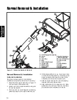
Страница 16: ...17 onto rear tractor frame spacers S 2 Attach cover B to support assembly using pins C and hair pins D 3 Pivot cover B up Install bags E by attaching grass bag hanger F to support assembly A Figure 17 Normal Installation Removal C P I N O M L J R A K 4 Lift discharge deflector J up Insert lower chute rod M into mounting plate L Pull strap I and secure by placing hole closest to knob in strap compl...

Страница 17: ...ower chute N from mounting plate L See that the discharge deflector J returns to the DOWN position 4 Remove hair pin D and pins C then remove cover B Note To prevent loss of parts reinstall pins C and hair pins D in support assembly hinge pivots E Figure 17 5 Remove hitch support assembly A from rear frame spacers S WARNING OPERATION WITHOUT BAGGER For operation without bagger the mower deflector ...

Страница 18: ...ved 500 N Spring Street PO Box 997 Port Washington WI 53074 0997 www MasseyLawn com MANUFACTURING INC 500 N Spring Street PO Box 997 Port Washington WI 53074 0997 www SimplicityMfg com 500 N Spring Street PO Box 997 Port Washington WI 53074 0997 AGCOLawn com PRODUCTS 535 Macon Street McDonough GA 30253 www Snapper com ...

Отзывы: