background image


36 


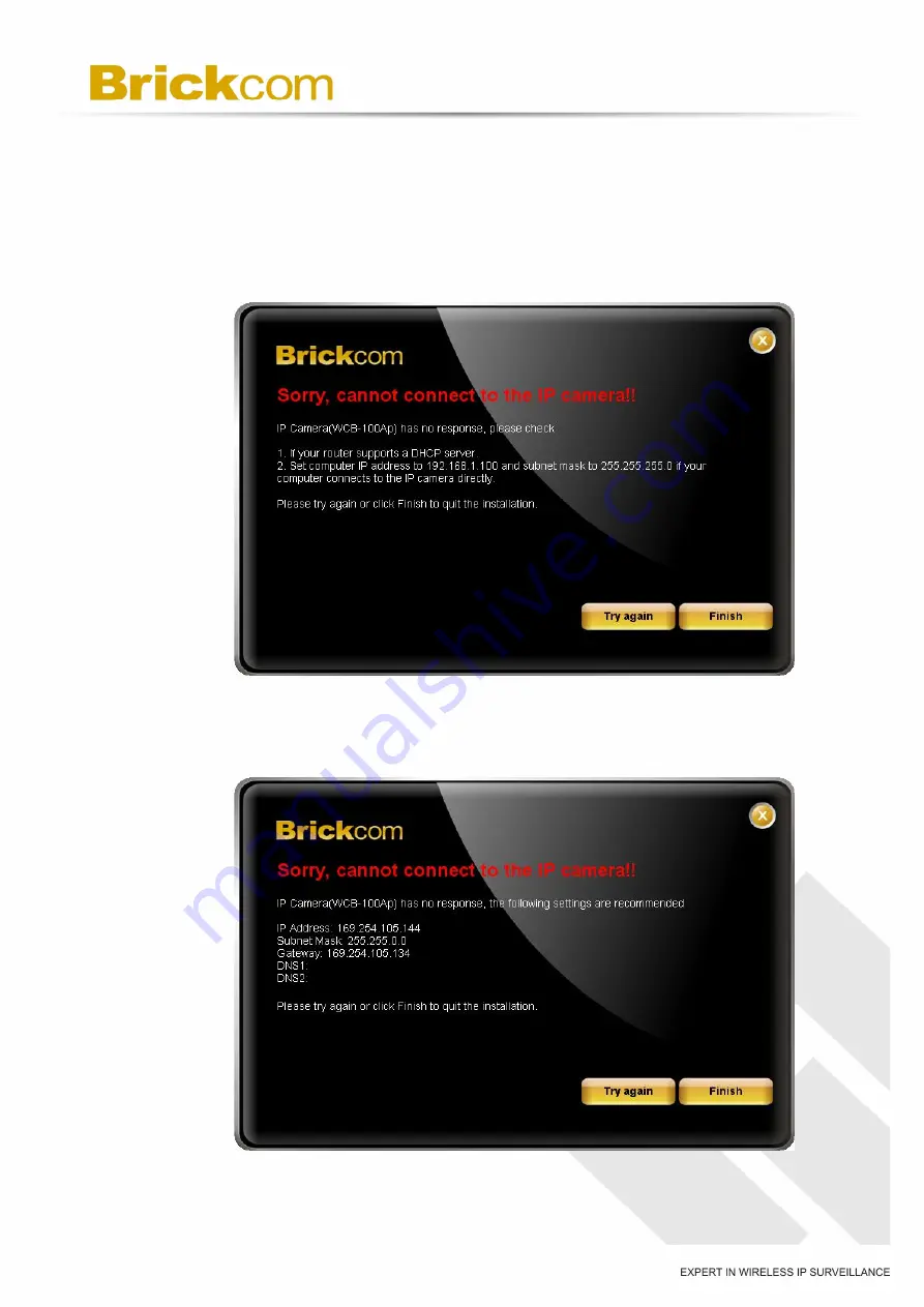
F.  When the IP address settings have been configured, the screen will either 

display a successful or failed connection message. If the connection failed, 

either try again or quit the installation. 

a.  If  “DHCP  IP  address  settings”  was  selected,  the  failure  page  will  be 

displayed as below: 


b.  If  “Static  IP  address  settings”  was  selected,  the  failure  page  will  be 

displayed as below: 

Содержание OB-130Np

Страница 1: ...Hardware User s Manual Megapixel Day Night Outdoor Bullet Network Camera Quality Service Group Outdoor Bullet V2 Series ...

Страница 2: ...100A V2 series OB 130N series into this User Manual Product name Network Camera Outdoor Bullet V2 series Release Date 2011 09 Manual Revision V3 0 Web site www brickcom com Email technical brickcom com info brickcom com 2011 Brickcom Corporation All Rights Reserved ...

Страница 3: ...du produit final 4 Chapter 1 Package Contents 6 Chapter 2 Outdoor Bullet Network Camera Overview 8 Chapter 3 Device Appearance Description 9 Chapter 4 Installation 13 4 1 Hardware Installation 13 4 2 Camera Connection 19 4 3 System Requirements 21 4 4 Software Installation 22 4 3 1EasyConfig 30 ...

Страница 4: ...ure that the operation of this camera is legal before installing this unit for its intended use Upon opening the product s package verify that all the accessories listed on the Package Contents are included Before installing the Network Camera read the warnings in the Quick Installation Guide to avoid misuse When installing the Network Camera carefully read and follow the instructions in the Insta...

Страница 5: ...t into an outlet on a circuit different from that to which the receiver is connected Consult the dealer or an experienced radio TV technician for help FCC Caution Any changes or modifications not expressly approved by the party responsible for compliance could void the user s authority to operate this equipment This device complies with Part 15 of the FCC Rules Operation is subject to the followin...

Страница 6: ...ant les mêmes canaux Les utilisateurs de radars de haute puissance sont désignés utilisateurs principaux c à d qu ils ont la priorité pour les bandes 5250 5350 MHz et 5650 5850 MHz et que ces radars pourraient causer du brouillage et ou des dommages aux dispositifs LAN EL Conformement a la reglementation d Industrie Canada le present emetteur radio peut fonctionner avec une antenne d un type et d ...

Страница 7: ...nditions ci dessus sont remplies des essais supplémentaires sur l émetteur ne seront pas nécessaires Toutefois l intégrateur OEM est toujours responsable des essais sur son produit final pour toutes exigences de conformité supplémentaires requis pour ce module installé NOTE IMPORTANTE Dans le cas où ces conditions ne peuvent être satisfaites par exemple pour certaines configurations d ordinateur p...

Страница 8: ... informations à l utilisateur final quant à la façon d installer ou de supprimer ce module RF dans le manuel de l utilisateur du produit final qui intègre ce module Le manuel de l utilisateur final doit inclure toutes les informations réglementaires requises et avertissements comme indiqué dans ce manuel ...

Страница 9: ...ackage Contents a Network Camera Outdoor Bullet V2 Series b Shielding Cover c Screw bag d Product CD e Warranty Card Easy Installation Guide f 2 Water Proof Connectors g Dry Bag h High Power POE Optional i Bracket Optional j Bracket Assembly Plate Optional k Wi Fi Dual Band Antenna package Optional l 3G Antenna package Optional ...

Страница 10: ...hen installing the Wi Fi antenna a Wi Fi Dual Band Antenna b Extension Cable c Surge Arrestor Kit d Mount Kit C Wi Fi Antenna Package contents Optional Refer to the installation guide included in the package when installing the 3G antenna a 3G Antenna b Extension Cable c Surge Arrestor Kit d Mount Kit ...

Страница 11: ...or excellent image quality without difficult procedures Support for Power over Ethernet enables the camera to use the same cable for power and data transmission eliminating the need to install an external power supply Installation for the WOB GOB Series models is not restricted by location or landforms The cameras offer various wireless options that make connecting to networks easier by adopting t...

Страница 12: ...9 Chapter 3 Device Appearance Description Front Panel Rear Panel Top ...

Страница 13: ...10 Bottom Side Micro SD SDHC Card Slot 3G SIM Card Slot ...

Страница 14: ...xtension I O terminal block which is used to connect the camera with external input output devices The pin definitions are listed as below Pin Function 1 Power 4 5V 2 Digital Output 3 Digital Input 4 Ground Pin Function 1 RS485 2 RS485 3 AC24V 4 AC24V DI DO Diagram ...

Страница 15: ...nd using a paper clip or thin object Wait for the camera to reboot To Restore Press and hold the Reset Button for ten seconds until the LED light turns off When successful restored the LED will be blue during normal operation NOTE By restoring the camera all settings will be restored to the factory default settings Micro SD SDHC Card Capacity The network camera is compatible with Micro SD SDHC Max...

Страница 16: ... and be damaged A Micro SD SDHC Card and 3G SIM Card Installation a Remove the Lens cover from the Bullet Camera b Inset the Micro SD SDHC card and 3G SIM card into their respective slots c Place a dry bag onto the camera device d Reattach the Lens cover and secure the cover to the top of the camera device using two screws ...

Страница 17: ...se a screwdriver and the supplied screws to secure the plate to the wall b Attach the Bracket Assembly Plate to the bottom of the camera using two screws c 1 Use the two supplied screws to secure the bracket to the side of the camera 2 Push back the spring on the mortise lock and hook the camera and attached bracket onto the groove of the wall mount bracket as shown in the diagram ...

Страница 18: ...with the camera Refer to step 3 for more details installation information e Secure the two screws on the wall mount bracket f Place the wall mount bracket on the plate and attach it using the supplied screws Adjust the angle of the wall mount bracket towards the area to be monitored ...

Страница 19: ... step 5 for instructions on how to install the Water Proof Connector Once the PoE cable has been constructed using the waterproof connector pass the RJ 45 cable from the camera through the bracket and connect it to the PoE cable RJ45 Connector 1 Pin No Function Pin 1 Transmit Out Tx Pin 2 Transmit Out Tx Pin 3 Receive In Rx Pin 4 DC 48V Pin 5 DC 48V Pin 6 Receive In Rx Pin 7 48V_GND Pin 8 48V_GND ...

Страница 20: ...instructions on how to install the Water Proof Connector Once the Ethernet cable has been constructed using the waterproof connector pass the cable through the bracket and connect it to the RJ 45 connector at the bottom of the camera RJ45 Connector 2 Pin No Function Pin 1 Power 4 5V Pin 2 Digital Output Pin 3 Digital Input Pin 4 Ground Pin 5 RS 485 Pin 6 RS 485 Pin 7 Audio in Pin 8 Audio out DIDO ...

Страница 21: ...efer to the installation guide included in the package when installing the Water Proof connector i Insert the stripped cable through the sealing nut and the housing Clamp the cable with an RJ45 plug ii Push the RJ45 plug into the housing and secure the sealing nut tightly iii Attach the gasket to the front of the housing iv Connect the Ethernet cable to the RJ45 cable v Secure the connectors tight...

Страница 22: ...nabled switch or a non PoE switch a If using a PoE enabled switch i Use a single Ethernet cable to connect the camera to the PoE enabled switch b If using a non PoE switch i Use a standard RJ 45 cable to connect the camera to a PoE Injector ii Use a standard RJ 45 cable to connect the PoE Injector to the non PoE switch iii Use a standard power cable to connect the PoE Injector to a power outlet ...

Страница 23: ...c If using a PoE injector as power input For GOB WOB Series i Use a standard RJ 45 cable to connect the camera to a PoE Injector ii Use a standard power cable to connect the PoE Injector to a power outlet ...

Страница 24: ...y 1024 MB or more Monitor 1024 x 768 pixels or more 24 bit True color or better Network Interface 10 100Mbps Network interface card must be installed Web Browser Microsoft Internet Explorer 6 0 SP2 or higher Adobe Reader Adobe Reader 8 0 or higher Audio The audio function will not work if a sound card is not installed in the PC Audio may be interrupted depending on network traffic ...

Страница 25: ... the camera There may be many cameras on the local network Differentiate the cameras using the serial number which is printed on the labels on the carton and the bottom of the camera A Insert the Installation CD into the CD ROM driver Run Auto Run Tool directly from the CD ROM to start the installation When installing the Brickcom software kit for the first time select a desired language for the i...

Страница 26: ...23 B In the Install Shield Wizard dialog box click Next to continue C Read the End User License Agreement and check the option I accept the terms of the license agreement Click Next to continue ...

Страница 27: ...em a If COMPLETE SETUP is selected i All program features will be installed into the default directory Check the option Complete and then click Next ii Click Change to change the appointed folder where installation and program files will be stored Click Next to continue ...

Страница 28: ...25 iii Select to create shortcuts Click Next to continue iv The installation information will be displayed Click Next to continue ...

Страница 29: ...aunching the PC NVR program please refer to the PC NVR user manual b If CUSTOM SETUP is selected i This option is recommended for advanced users It can be used to install the system to a preferred directory or to select specific program feature s ii Check the option Custom and then click Next ...

Страница 30: ...27 iii Select the features to install Click Next to continue iv Click Change to change the appointed folder where installation and program files will be stored Click Next to continue ...

Страница 31: ...28 v Select programs to create shortcuts Click Next to continue vi The installation information will be displayed Click Next to continue ...

Страница 32: ...29 E To launch EasyConfig or PC NVR Standard select the application and click Finish When launching the PC NVR program please refer to the PC NVR user manual ...

Страница 33: ...oftware installation and an EasyConfig icon was not installed on the desktop the program will be installed under C Program Files Brickcom EasyConfig unless the program was saved to a preferred directory A Click Start to continue The program will automatically search for the camera in the intranet NOTE Check Skip the hardware installation guide to skip checking the hardware connection To check the ...

Страница 34: ...31 ...

Страница 35: ...ode or Professional Mode to obtain the camera s IP settings If Simple Mode is selected EasyConfig will set up the connection automatically If Professional Mode is selected the user will need to configure the IP settings manually ...

Страница 36: ...as using their UPnP name Double click on the camera from the survey list to connect D For configuring the IP address settings select either Settings remain the same Automatically obtain an IP Address DHCP or Set IP Address configuration manually The DHCP setting is recommended ...

Страница 37: ...34 If Set IP Address configuration manually is selected the following pages will be displayed ...

Страница 38: ... which allows users to assign a unique EasyLink name to their network camera s IP address There is no need to configure the router to open up ports or remember hard to memorize IP addresses Users can log onto uniqueEasyLinkname mybrickcom com to view the camera s web GUI and live view a Enter a unique EasyLink name whose length must be between 5 32 characters b When finished click the arrow button...

Страница 39: ...y a successful or failed connection message If the connection failed either try again or quit the installation a If DHCP IP address settings was selected the failure page will be displayed as below b If Static IP address settings was selected the failure page will be displayed as below ...

Страница 40: ... PC NVR program Live View to view the live video from the connected IP camera or X in the top right corner of the screen to close the installation window If the user starts the PC NVR program please refer to the PC NVR user manual Once installation is complete the Administrator should proceed to the next section Accessing the Network Camera for necessary changes and configurations ...

Отзывы: