background image

 47 

Treadwall Kore Pro Owner’s Manual—2017 

5. WHAT IS NOT COVERED 

a. Normal wear and tear is excluded from this warranty. No warranty shall be provided in the event the Tread-

wall is modified by original purchaser, for parts not approved by Brewer's Ledge Inc., or for warranty-related 
service other than by personnel authorized by Brewer's Ledge Inc. 


b. Damage incurred by negligence during movement, assembly, or breakdown of the Treadwall by the Original 

Purchaser or personnel contracted by the Original Purchaser is excluded from this warranty. The sale of spe-
cial tools and instructional materials to the Original Purchaser and any training of the Original Purchaser's 
staff by Brewer's Ledge Inc. related to the movement, assembly and break-down of the Treadwall does not 
imply any warranty against Original Purchaser negligence and does not void this exclusion.  Brewer's Ledge 
Inc. reserves the sole right to determine the origin of damage as related to this provision.


6. LIMITATION OF DAMAGES AND IMPLIED WARRANTIES 

a. Except as provided herein, Brewer's Ledge Inc. makes no express warranties; implied warranty of merchantabil-

ity or fitness for a particular purpose is limited in its duration to the duration of the written limited warranties set 
forth herein. 


b. In no case shall Brewer's Ledge be liable for any special, incidental, or consequential damages based on breach 

of warranty, breach of contract, negligence or any other legal theory.  Such damages include but are not limited 
to, loss of profits, loss of use of the equipment or any associated equipment, the cost of capital, the cost of sub-
stitute equipment, facilities or services, downtime, the claims of third parties, including customers, and injury to 
property. 


This limitation does not apply to claims for personal injury where such limitation would be a violation of the applica-

ble law. Some states do not allow the exclusion or limitation of incidental or consequential damages, so the 
above limitation or exclusion may not apply to you. 


7.  TERMS OF WARRANTY 

The terms and conditions of this warranty are applicable as between Brewer's Ledge and Original Purchaser to the 

sale of Treadwall equipment to Original Purchaser. 


STATE LAW RIGHTS


This warranty gives you specific legal rights, and you may also have other rights, which vary, from state to state. 


Copyright 2017, Brewer Fitness Inc. 

Treadwall® Limited Warranty 

Содержание Treadwall Kore Pro

Страница 1: ...COMPLETE OWNERS MANUAL Treadwall Kore Home Model Brewer Fitness 87 York Ave Randolph MA 02368 USA 781 961 5200 www brewerfitness com ...

Страница 2: ......

Страница 3: ...es the benefits of vertical movement links resources about how to integrate the wall into fitness routines useful incentive programs to help ramp up popularity and much more The workout is effective fun and customizable so now it is up to you all to extend the knowledge to your members and get them to try it out Once the initial attempt is out of the way people will see for themselves what a worko...

Страница 4: ...not order the angle changing kit there are two lower uprights that take the place of the jacks and have several optional angle choices to use These are self evident and need little explanation These instructions may have several references to the Kore Pro we use universal instructions at times that may reference either the Kore Home of Kore Pro Both units have similar construction within the basic...

Страница 5: ...he wall downwards With our auto stop technology if you stop climbing the Treadwall will stop and wait for you The Treadwall will not move unless you are on the wall and climbing upwards You can adjust the angle of the wall as well which makes it easy to cater to a large variety of abili es and fitness goals For ARC training and general endurance work s ck to easier angles for power endurance or hig...

Страница 6: ...ngle Changing On the Kore Pro there are three angle ranges Your range will be chosen during assembly If your kore is bolted in the top hole you can go from a 5 degree to a 20 degree overhang The middle hole goes from 13 to 28 and the bo7om hole goes from 20 to 35 degrees Many gyms will allow anybody to change the angle and some will set an angle when se3ng new routes and leave it To change the ang...

Страница 7: ...alories 0 00 00 0 1 2 3 4 5 6 7 8 9 0 Clear Home Screen The home screen shows real me data for a single climb When you pause for 5 seconds the counter will hold your data on the screen un l you begin climbing again and then it will start from where you le off To reset the counter for a new climber hit Reset Setup Screen To set a distance or me goal tap or hold the bu7ons labeled Distance Goal or Ti...

Страница 8: ...ulder problems that also use the start hold for the finish Users can then link boulder problems together to create routes of varying length and difficulty Similar to se3ng for circuit bouldering you can also mark a longer route with tape numbering the holds along the way to create a unique long routes Usually in this set up you won t use tracking for foot holds This also makes for a great li7le compe...

Страница 9: ...10 Treadwall Kore Pro Owner s Manual 2017 ...

Страница 10: ...s standing and not climbing upwards The sensor for this system is located at the bo7om right side of the machine There is a small switch which closes an electronic valve in the hydraulic system The panels slide through the side channels on small plas c bu7ons which help reduce fric on in the system These bu7ons are located on the top front face and the bo7om rear corner of each panel Bu7ons only n...

Страница 11: ...lean machine Maintenance Schedule How to access the inside of your Treadwall The Treadwall wall panels are bolted to a set of chains These two chains form a con nuous loop around the top and bo7om axles Each panel is a7ached to flanges mounted on the chains with 4 Philips head bolts and 3 8 lock nuts Rotate the wall so that the desired panel is lined up with the access hole Remove cover then remove...

Страница 12: ...n and receiving adequate power Pg 18 Wall is sluggish lighter weights will not pull wall down Either the drive chain too ght the channels need lubrica on or the ends of the panels are rubbing the channels Loosen the drive chain Pg 17 lubricate the Treadwall Pg 19 and check the internal x bracing Pg 16 Hold rotates Hold bolts not sufficiently ght ened Re check hold bolts re ghten with a 5 16 Allen Wr...

Страница 13: ...posite corner of the bo7om horizontal This measurement will perfectly square the machine on a level floor If your floor is not level or you are having trouble making an accurate measurement you can use a level on the side channel of the Kore or across the panels to adjust the x bracing Measure from corner to corner to ensure that each x brace is the same length On a level surface the length will be ...

Страница 14: ... it with your finger at the inspec on hole There should be no slack but not too ght CAM PULLEY CABLE ADJUSTER Speed Lever Adjustment 1 Adjust the speed lever to the slowest posi on 2 The hydraulic unit is at the top of the right channel Remove the cover two screws 3 Note the cam and pulley that together control the valve With the lever at slowest posi on the pulley should be at the highest point of...

Страница 15: ... the microswitch needs to be inspected further or replaced remove the plas c access hole cover and all nuts and washers from the microswitch Reach inside of the access cover and unclip the electrical wire from inside the channel and pull the microswitch out Counter Sensor Adjustment 1 Remove 1 or 2 panels 2 Rotate panel gap to reveal sprocket and sensor assembly on right side of machine 3 Inspect ...

Страница 16: ...e lubricated Two in the front and two in the back Each channel has a rear surface and a front surface 3 To lubricate the rear surfaces fig 1 put the nozzle into the gap between two panels and squirt a li7le bit of grease onto the rear channel surface Do this for all the gaps in the front and rear of the Treadwall about 70 gaps total 4 To lubricate the front surfaces fig 2 put the nozzle in between t...

Страница 17: ...n but the display and auto stop will not work Fromright side frame top or bottom depending on unit the power wire enters the right channel where it is connected to the interior wiring during assembly Fromthis connection 9 volt DC power goes to both the auto stop systemand the display For the auto stop system negative voltage goes to the solenoid valve in the hydraulic unit and positive voltage is ...

Страница 18: ...26 Treadwall Kore Pro Owner s Manual 2017 ...

Страница 19: ...r s Manual Provide a general overview of the basic opera ons and usage to new Treadwall users Do not place other equipment or any items in the fall zone or onto the floor mat of the Treadwall Kore Pro Specifica ons Weight 1150 Pounds Dimensions 85 wide x 96 deep x 145 tall Width of climbing surface 6 feet Length of climbing surface 22 feet Number of hold Placements 308 Angle Range Nega ve 5 degrees ...

Страница 20: ... area of a gym Tools required and set up In addi on to the tool list you will need a helper and two ladders If you are ght on space begin by assembling the frame work and then bring in the side channels and shroud and place them directly onto the machine Assembly will take 6 8 hours please read the en re assembly procedure prior to star ng the install If you do have ques ons please contact us at 1...

Страница 21: ...e Assembly 1 2 3 4 5 1 X brace components The two short pieces and two long pieces are packed with the channels the turnbuckles are in the hardware box 2 Spines 3 Feet 4 Jacks 5 Horizontals 6 Uprights 7 Bolt bags Kore 1 and Kore 3 Parts Needed 6 7 ...

Страница 22: ...g the horizontals to the spines being careful to make sure that the spines are oriented correctly with the small extensions facing inwards Make sure to include the x bracing strips when bol ng the horizontals to the spines Use the bolts in bag Kore 1 The shorter pieces are bolted to the lower por on of the frame and the longer strips are a ached at the top You adjust the length of the turnbuckles ...

Страница 23: ...se enough to freely pivot but ght enough to resist any side to side movement Next a7ach the jack assemblies to the spines Place a bolt into the top a7achment using the hole closest to the floor Make sure the cranks face outside of the wall Make sure that the head of the bolt is on the outside of the upright Do not put a nut onto this bolt yet If you don t have the room to lay out the uprights as sh...

Страница 24: ... the jack first so that the nut is on the outside of the Treadwall If you are combining li ing the frame with a7aching the jacks have a helper hold the frame in place as you bolt first the top then the lower bolt Make sure to leave the nut and washer off of the top bolt that connects the jack assembly to the frame Leave the nut and washer off of this joint ...

Страница 25: ... Kore Pro Owner s Manual 2017 Main Channel Assembly 1 2 3 4 5 1 Top Shroud 2 Bo om Shroud 3 Panels 4 S ffies 5 4 chain boxes 6 Upper sha 8 Le channel 7 Lower sha 9 Right channel 10 Spacer bar Parts Needed 7 8 6 9 10 ...

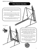
Страница 26: ...e apart Quickly add a washer and lock nut to the bolt so that the channel can not fall off Use the bolts in the Kore 2 Bolt bag to fully a7ach the channel to the spine Spine Moun ng Holes Top of channel Front of channel Place the lower sha into the bearing of the right channel The bearings can swivel so it is ok for the other side of the sha to rest on the floor One sprocket on the lower sha is le l...

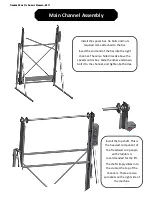
Страница 27: ...t Let the channel hang and get the bo7om shroud and the remaining bolts from the Kore 2 bag Place the bo7om shroud roughly in posi on make sure the flat por on of the side plates is oriented upwards Swing the le channel backwards keeping the bo7om shroud aligned with the outside of the channel Bolt the channel to the spine a7achments and then bolt the bo7om shroud to the channels using hardware bag...

Страница 28: ... right channel There is a hole directly above the speed control box Slide the other end down bolt it to the channel and ghten both sides Install the top sha This is the heaviest component of the Treadwall so 2 people with 2 ladders is recommended for the li The sha simply slides into the slots at the top of the channels There are two sprockets on the right side of the machine ...

Страница 29: ...r and nut on the inside of the wall Tighten the lower rear bolt but leave the front two loose and back them out as much as possible With two people raise the top shroud and slide the curved slots between the flange on the bolts and the sha bearings The shroud will be on the outside of the bearings The brush goes to the front of the Treadwall Once the shroud is in place put the last bolt through the...

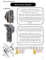
Страница 30: ... chain but don t make it too ght Too much tension will make the Treadwall run sluggishly Pushdown Bolt To disassemble the master links use a pair of pliers or a flat blade screw driver to press and slide the retaining clip along the side plate in the direc on opposite the open end of the retainer clip To install the Master links assemble them as shown in the diagram below The retaining clip must fit...

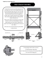
Страница 31: ...f the tabs fig 1 Bring the other end around the sprockets on the lower sha A7ach the master link When you are doing the second chain be aware that the tabs must be synchronized between the two chains When a tab on one chain is level with the spacer bar the tab on the opposite chain must also be level fig 2 If the chains are not synchronized the panels will be crooked and jam fig 1 fig 2 Strong springs...

Страница 32: ...the sha on the inside of the channel should be adjusted so that the magnets pass about 1 8 above the sensor Mount the counter mer on the right channel to the four small holes below the speed control with the provided screws and nuts The sensor wire and power wire are pre installed and plug directly into the rear of the counter Plug the power supply into the wire coming out of the plas c cover at t...

Страница 33: ... and a socket wrench with a 3 8 socket Do not over ghten the screws If your drill has a clutch use a low se3ng so that the head of the screw seats down but does not dig into the panel No ce the plas c wear bu7ons in the corners of the panel The bu7ons in the front of the panel should always be at the TOP corners of the panel The final hole pa7ern on the climbing surface should create a diamond shap...

Страница 34: ...els in the front When this happens always use blocks of wood between the bo7om panels and channel flange It is safest to do this on both sides as shown to jam the wall and prevent it from backing up The last three panels cannot be put in the same way They must be put in from the bo7om slid up to meet the other panels and bolted on Remove the covers from the rectangular access holes at the bo7om of ...

Страница 35: ... panel Install the Ladder Line first Followed by the climbing holds there is a short guide in this manual Page 8 and 9 When everything is in place test the wall at different angles and speeds Finally put on the last panel and cover the access holes a er doing the tests on the following page Slide the mat under the wall to the back of the frame with the shortest fold to the rear ...

Страница 36: ...the angle of the Treadwall until the prop fits under the support arm as shown Lower the wall onto the prop until the weight is off of the jack 3 Remove the locking bolt You can now adjust the jack to line up the desired hole with the inner hole The bottom of the three holes is the steepest range and the top hole is the least overhang 4 Replace the locking bolt and crank up the jack slightly to tak...

Страница 37: ......

Страница 38: ...set at the factory but it can be adjusted for sensi vity if required by loosening its small moun ng screws and pivo ng it 3 Check the drive chain at the top of the right channel The slack should be adjusted out of it but it should not be too ght A er climbing for a few minutes some slack might develop which should be adjusted out This chain will stretch over me and should be adjusted a er about a ...

Страница 39: ...bers progress Jacks The mechanism that allows you to change the angle on a Kore Ladder Line A wooden climbing hold that allows for easy and aerobic climbing Mat A foam pad which protects falls placed under the Treadwall Panel A wood board that forms the surface of the Treadwall Shroud A cover at the top of the Treadwall Speed The rate at which a climber moves the wall down Spine The F shaped side ...

Страница 40: ...e the Treadwall will be free from any defect in materials or workmanship For M4 M6 Kore Commercial models Structural Steel Frames and Welds Ten years parts and labor and freight All other components except cords floor mats and vinyl products One year parts labor and freight Cords side covers floor mats Ninety days parts labor and freight For M4 and KORE Home Residential models Structural Steel Fra...

Страница 41: ...ranties implied warranty of merchantabil ity or fitness for a particular purpose is limited in its duration to the duration of the written limited warranties set forth herein b In no case shall Brewer s Ledge be liable for any special incidental or consequential damages based on breach of warranty breach of contract negligence or any other legal theory Such damages include but are not limited to l...

Страница 42: ...adwall Kore Pro Owner s Manual 2017 Contact Informa on Website WWW BREWERFITNESS COM Email SALES BREWERFITNESS COM Address Please come by for a visit some me 87 York ave Randolph MA 02368 Phone 1 800 707 9616 ...

Отзывы: