background image

 BREN 700-Series User Manual 

The Control Panel      

3-1

Chapter 3    The Control Panel 

This chapter describes the button operations with the LCM menu flowcharts of 

the BREN 700-

Series  Razor

  When  the  cutting  plotter  is  ready  for  use  as  described  in  Chapter  1  &  2,  all 

functions are under default parameters.   

3.1 

The LCD Panel 

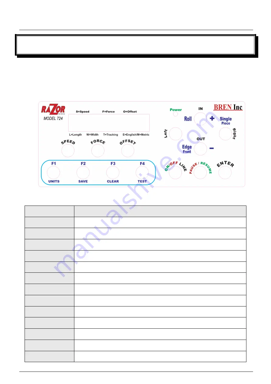
< LCD Control Panel on 

BREN 700-Series Razor

Key 

Function 

LCD Screen 

To display functions and error messages. 

Power LED 

To indicate the power status ( light up: power on; light off: power off ) 

4 Arrow Keys 

To move position, select function, or change setting. 

ENTER 

To set item or register the immediately preceding input value. 

PAUSE/RESUME  To temporarily halt cutting process or to continue 

ON/OFF LINE 

To switch modes, stop cutting job, or abort changes of settings. 

OFFSET 

To adjust the value of blade’s offset. 

FORCE 

To adjust the value of cutting force. 

SPEED 

To adjust the value of cutting speed and quality. 

F4

 TEST 

To perform cutting tests on different media. 

F3

 CLEAR 

To clear up buffer memory. 

F2 Save

To select tools. 

F1 Units


To set up functions. 

Содержание Razor 700 Series

Страница 1: ...V1 NOV 2016 BREN 700 Series Razor User Manual BREN Inc 1 800 826 3991 8256 Horton Highway College Grove TN 37046 www BrenInc com All rights reserved 2016 Quality Marking Products Since 1972...

Страница 2: ...uch any of the moving parts of this machine such as the carriage Also be careful to make sure that clothing and hair do not get caught Always connect the power cable to a grounded outlet Always use th...

Страница 3: ...ctures shown below O CORRECT X INCORRECT Press down DISABLE Press down Stop bar ENABLE Pull up bottom to release grip Note In case the grips clipped together due to your wrong operation please use a p...

Страница 4: ...s 24 inches BREN 740 for media width 2 inches 40 inches BREN 752 for media width 2 inches 52 inches 1 2 Package Items Standard Item Q Qu ua an nt ti it ty y 1 Cutting Plotter 1 2 Stand Set for BREN 72...

Страница 5: ...1 piece of AC power Cord 1 piece of data cable USB cable 3m 1 set of Blade Holder Assembly Installed in tool carriage of the cutting plotter 1 piece of Blade Installed in Blade Holder 1 piece of Safe...

Страница 6: ...eys and 1 LED and 1 LCM showing messages and menus Cutting Strip provides the protection of blade when the blade is cutting Carriage performs the cutting with the installed blade and pen with AAS modu...

Страница 7: ...gure 1 3 Roll Holder holds and supplies the roll media for cutting Roll Holder Guide Bushes serve to keep the roll media in place when media is pulled from the roll T Stand supports the cutting plotte...

Страница 8: ...nsert the AC power cord Power Switch On when switches to I Off to O Figure 1 4 Serial Interface Connector RS232C used to connect the cutting plotter to a computer through a serial interface cable Figu...

Страница 9: ...d easily from any direction Keep enough space for the machine accessories and supplies Keep the working area stable avoiding sever vibration Keep the temperature between 15 and 30 60 86o F in the work...

Страница 10: ...roll holder 2 pieces 2 pieces of base beams 2 pieces of side beams 1 piece of stand beam 2 pieces of roll holder support 20 pieces of M6 screws 1 piece of M5 L shape hexagon screw driver 1 piece of i...

Страница 11: ...on the T stand and follow number to assemble See Figure 2 2 4 2 2 5 There is hexagon socket head screws fasten on the T stand on both side taken as locating pins Step 4 Position the stand beam perpen...

Страница 12: ...under the plotter on the bottom of the plotter there is one hole on each side in the position corresponding to the locating pins so the locating pins can be located into the holes Then insert the scre...

Страница 13: ...the stand and then tighten them up as shown in Figure 2 2 7 You could decide roll holder support s position by inserting into different holes Step 7 Place the roll holder 1 onto the roll holder suppor...

Страница 14: ...npacking roll holder 2 Figure 2 2 9 Step 9 Insert the end of the roll holder without the damper into the left roll holder support and then insert the end of the roll holder with the damper into the ri...

Страница 15: ...the damper until it is securely attached to the right roll holder support Figure 2 2 11 Step 11 Lastly the complete picture will be shown like below Figure 2 2 12 Step 12 Please refer to user manual s...

Страница 16: ...y for the stands with Flexible Media Support System only Step 1 Insert the cable tie into the upper hole of cable saddle from bottom to top This side up Step 2 Place the USB cable into the cable tie a...

Страница 17: ...BREN 700 Series User Manual Installation 2 9 Untied way pull out the cable tie pull up the pin release the cable tie Pull out the cable tie Pull up the pin Release the cable tie...

Страница 18: ...ape hexagon screw driver 1 piece of M5 L shape hexagon screw driver 1 piece of M6 L shape hexagon screw driver for adjusting the screws of Roll Holders 1 piece of Installation Guide for Roll Holder St...

Страница 19: ...rt assembly and tighten them with M6 L shape screwdriver Like Figure 2 3 3 Step 5 Place the two roll holders into the holes of Roll Holder Support Figure 2 3 4 To install the roll holder with damper p...

Страница 20: ...2 12 2 5 Instruction of Damper Roller Turn the wheel as instructed below to adjust damping The bigger the number is the stronger the damping The volume symbol sticker indicates the damping level Figu...

Страница 21: ...motor failure which is not covered under warranty If however the blade is not extended ENOUGH it will not be able to completely cut through the material Knowing the CORRECT amount of extension for you...

Страница 22: ...BREN 700 Series User Manual Installation 2 14 Step 4 Insert the blade holder into tool carriage Please note the outward ring of the holder must put into the grooves of carriage firmly...

Страница 23: ...USB interface are based on the Universal Serial Bus Specifications Revision 2 0 Full Speed 2 7 2 Connecting your BREN 700 Series Razor cutter 1 Turn on the machine 2 Connect the USB connector to the m...

Страница 24: ...you will have the option to install the 32 or 64 bit version of the Windows driver for your BREN Razor If you do not know which version you are currently running see section 3b on the next page NOTE W...

Страница 25: ...either the 32 or 64 bit version of the driver to download depending on what version of Windows you are running If you aren t sure you can open your start menu and right click This PC or My Computer ri...

Страница 26: ...efault to C Program Files x86 WinLINE Bren OEM Edition unless you set a new location for the driver to be installed Once you ve decided where to install the software select Next to continue 6 Once the...

Страница 27: ...l and activate the driver you MUST use the WinLINE Installation Wizard Once the cutter is connected to your PC via USB click the box next to The printer IS plugged in and then select Next to continue...

Страница 28: ...cut widths for the corresponding cutter For example if you set a BREN 752 up as a 724 on your PC you will only be able to cut up to 24 inches instead of the 52 the cutter is capable of and the driver...

Страница 29: ...hen attempting to activate the software contact BREN technical support at 800 826 3991 or info breninc com 2 8 1 RS 232 Serial Interface Connecting to the RS 232 Serial Port 1 For IBM PC PS 2 users or...

Страница 30: ...key and scroll right until you see DHCP and press the Enter key 5 DHCP option should show disabled Press the Enter key again to enable it 6 After the DHCP is enabled your display screen should show a...

Страница 31: ...llation 2 23 10 When the Add a Device screen is displayed select The printer I want isn t listed 11 When the Find a printer by other options screen is displayed select Add a printer using a TCP IP add...

Страница 32: ...rea next to Hostname or IP address enter the IP address from your BREN 700 Series that was displayed on your screen when you enabled DHCP The same address or a variation of it that may add a number or...

Страница 33: ...he process If the Add a Printer screen is displayed after you select Cancel you can select Cancel again to exit the process 15 Now that the network port is created follow the standard steps to install...

Страница 34: ...and verify with your IT department nothing on your network is blocking the device from communicating with your device on the network 23 Port setup and driver installation will have to be done on each...

Страница 35: ...nu select Printer Properties 2 Choose the About Help tab and verify that your serial number appears and is correct This indicates that you successfully activated the driver software Select OK and clos...

Страница 36: ...will establish the initial page settings for your BREN 700 Series Razor You can change the settings as needed per job once you are in any application you are using to send a cut job to your BREN cutt...

Страница 37: ...pinch rollers your cut width will be less than the actual width of your material For example if you are using 18 material the left and right pinch rollers utilize at least on each side of the material...

Страница 38: ...LED To indicate the power status light up power on light off power off 4 Arrow Keys To move position select function or change setting ENTER To set item or register the immediately preceding input va...

Страница 39: ...4 F 2 80 O 0 011 L 984 2 W 10 8 T1E Sending data PAUSE FORCE Force 80 gf OK ENTER use to select ENTER to enable the setting SPEED Speed 72 cm s Select OK ENTER Up Speed 72 cm s Select OK ENTER Quality...

Страница 40: ...h an increment of 3 cm s Quality Normal Select OK ENTER Up Accel Medium Select OK ENTER High Medium Low Speed 72 cm s Select OK ENTER Square Cut Select OK ENTER CUT TEST Repeat AAS Job Select OK ENTER...

Страница 41: ...t OK ENTER Enabled Disabled First Back To Origin Select OK ENTER DHCP Select OK ENTER Enabled Disabled IP Address Select OK ENTER IP Address set Submask set Gateway set MAC Address 00 CF 52 72 03 01 E...

Страница 42: ...resume the process by press Pause Resume key again ONLINE OFFLINE 1 To switch between online mode and offline mode 2 To stop the cutting job or abort the change of setting Once press this key the cutt...

Страница 43: ...to return to the main menu This option will appear after finishing reading all registration marks Pattern Setting To provide two patterns for cut test Note It is recommended to select Cross if you are...

Страница 44: ...of the rolled media is less than 2 meters or the weight is light it is recommended to set this mode disabled Enable Rear Paper Sensor To detect if the rear paper sensor is covered to determine the fo...

Страница 45: ...splay the version number of Firmware and FPGA code Select Language To select displayed languages on LCM panel in English Spanish Italian Deutsch Portuguese Polish Turkish or French English Select Unit...

Страница 46: ...pinch rollers are raised Figure 4 1 Step 2 Load your media on the platen and slide it under the pinch rollers from either the front side or the backside The alignment rulers on the platen extension wi...

Страница 47: ...4 Push the lever backward to lower down the pinch rollers Step 5 Turn on the power the tool carriage will measure the size of the media automatically And the plotting cutter begins to work Note 1 Alwa...

Страница 48: ...m of all pinch rollers Figure 4 5 before the lever is pushed backwards to ensure accurate media width detection 4 1 2 Loading the Roll Media Step 1 Put the roll holder guide bushes on two roll holders...

Страница 49: ...edia is firmly gripped see Figure 4 7 Then put the roll media on the roll holders Adjust the position of the roll media ensure that media flanges are able to run in the grooves of roll holder guide bu...

Страница 50: ...rid drums Step 6 Push the lever backward to lower down the pinch rollers Step 7 Fix roll holder guide bushes on the roll holder to secure the roll media Step 8 Turn on the power switch and select Roll...

Страница 51: ...the media length is less than 4 meters leave the margin of 0 5mm 25mm in the left and right edges of the media Figure 4 12 If the media length is greater than 4 meters leave at least 25mm margin on t...

Страница 52: ...et at the cutting test position When the cutting test is completed a pattern appears Peel off the pattern to see if it can be easily separated from the media base If yes the setup tool force is approp...

Страница 53: ...pecification About the Tool in Appendix After you notice all the above you ll enjoy your gigantic signs production 4 6 When Completing the Cutting Job After completing the cutting job raise the sheet...

Страница 54: ...er surface with a lint free cloth If necessary with a damp cloth immersed in water or alcohol Dry and wipe any remaining residue off a soft lint free cloth Wipe all dust and dirt from the tool carriag...

Страница 55: ...ch Rollers 1 If the pinch rollers require a thorough cleaning use a lint free cloth or cotton swab to wipe away the accumulated dust from the rubber portion of the pinch rollers To prevent the pinch r...

Страница 56: ...cord connected to the power connector properly Does the power LED still illuminate Solutions If the LCM is able to display the message the cutting plotter should be in a normal condition Switch off t...

Страница 57: ...ssage indicates that there might be a problem on the X axis Check if the drum is working well and if the media is well loaded Correct the problem and re power on to reboot system This message indicate...

Страница 58: ...etting been done correctly Refer to Section 2 7 2 Connecting your cutting plotter Yes No Try the communication between your cutting plotter and computer If it still does not work have your cutting plo...

Страница 59: ...nd using a different cable Does the software vendor provide a sample file Most well known cutting softwares in the world have drivers for our cutting plotters If not use software that has HP GL and HP...

Страница 60: ...in an optimum blade force Refer to Chapter 4 3 Cutting Force and Offset Adjustment Is the tool offset set up properly Yes No Adjust the tool offset to obtain an optimum value Is there any dirt adhered...

Страница 61: ...ry Buffer 32 MB 16 MB when using AAS Interfaces USB 2 0 Full Speed Serial RS 232C and Ethernet Type of Command HP GL HP GL 2 Mechanical Resolution 0 006 mm Software Resolution 0 025 mm Distance Accura...

Страница 62: ...ct has been opened or serviced in any way by other than BREN service technicians or a BREN Authorized Service Location No other warranty either expressed or implied is valid 2 PRODUCT INSURANCE PROGRA...

Отзывы: