background image

Installation

 TDB3105

Bradley • 215-1563 Rev. E; ECN 12-00-004 

1/15/2013 

21

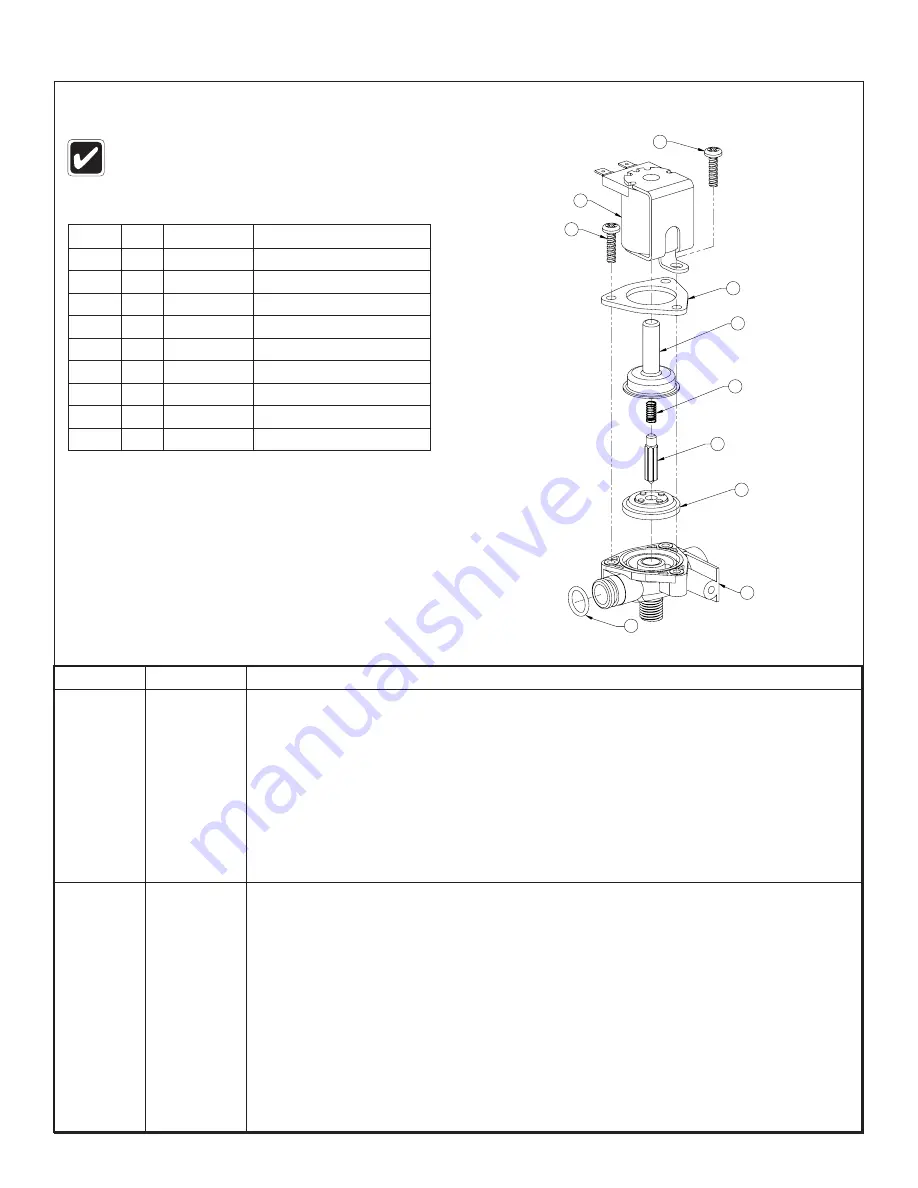
Solenoid Valve S07-069 (closed body)

Problem

Cause

Solution

An individual 

operating 

station fails 

to shut off 

and drips.

Debris is 

trapped 

between the 

diaphragm 

and the valve 

seat.

Remove debris between diaphragm and the valve seat.

1.  Remove the three #8 Phillips-head screws that hold the solenoid valve assembly together. Be 

careful not to lose the armature or spring.

2.  Remove the diaphragm. Remove any particles that have been trapped between the 

diaphragm and the valve seat. Rinse off the diaphragm and inspect for damage. Make sure 
the center orifice and both small side orifices are open.

3.  Reassemble in reverse order (do not overtighten the Phillips-head screws or the plastic valve 

body may crack). Tighten until the armature plate makes contact with the plastic body.

4.  Reconnect the wiring.

An individual 

operating 

station fails 

to turn on.

A failed coil for 

the valve or 

loose electrical 

connection to 

the terminal.

Test the station to determine the cause.

1.  Disconnect the wires from the coil of an adjacent valve. Disconnect the wires from the 

problem valve and reconnect to the adjacent valve.

2.  Turn on electrical and water supplies to the unit. Pass your hand in front of the sensor of the 

problem station, and the adjacent station should turn on.  

If the adjacent station turns on and cycles normally, replace the coil on the problem valve.

If the adjacent valve fails to turn on, inspect the wires from the sensor cable and do the following:

• 

make sure there are no breaks and that the fully insulated disconnect terminals are firmly 
crimped in place;

• 

turn off the electrical and water supplies;

• 

reconnect to the adjacent valve and turn on the water supplies to the unit;

• 

pass your hand in front of the sensor. If the station still fails to turn on, replace the sensor.

Item

Qty.

Part No.

Description

1

1

118-308

Valve Body, 5/16" Closed

2

1

269-983

Diaphragm

3

1

269-577

Armature

4

1

269-578

Spring

5

1

269-1729

Armature Housing

6

1

269-1730

Clamp, Armature Housing

7

1

269-1797

Coil, Solenoid Valve

8

3

160-447

Screw, #8 x 5/8"

9

1

125-165

O-ring, #2-013

Turn off water supplies to the unit before 
troubleshooting.

1

2

3

4

5

6

7

8

9

8

Содержание TDB3105

Страница 1: ...tenance 17 18 Sprayhead Parts List and Troubleshooting 19 TouchTime Troubleshooting 20 Solenoid Valve Troubleshooting 21 Thermostatic Mixing Valve Troubleshooting 22 Available in standard height juvenile height and TAS height IMPORTANT Read this entire installation manual to ensure proper installation When finished with the installation file this manual with the owner or maintenance department Sep...

Страница 2: ...pplied OPTIONAL Bradley recommends installing an electrical cut off switch to the unit This feature allows no accidental water delivery during regular maintenance and service Pre Installation Information Terreon Material The Washfountain is constructed of Terreon a densified solid surface material composed of polyester resin Terreon is resistant to chemicals stains burns and impact Surface damage ...

Страница 3: ...ile TAS Height 36 Circular with Optional Accessories Adjust to Towel Dispenser Mounting Holes 6 152 59 1499 w Soap 50 1 2 1283 w o Soap 51 1 8 1299 42 3 4 1085 39 1 8 994 30 762 23 1 2 597 18 1 2 470 36 914 9 3 4 248 mm Adjust to Towel Dispenser Mounting Holes 6 152 53 5 8 1362 45 1 4 1149 41 5 8 1057 34 864 23 1 2 597 18 1 2 470 36 914 9 3 4 248 8 3 4 222 61 1 2 1562 w Soap 53 1346 w o Soap Model...

Страница 4: ...Above Floor Cold Hot 4 1 8 105 2 NPT Drain Stub Up 3 76 Above FLoor 2 51 4 3 4 121 3 7 8 98 5 127 Suggested Electrical Outlet Location 36 914 Bowl Type B Centrally rising vent with supplies from above 1 2 Nominal Copper Tubing Supplies from Above 7 8 22 7 8 22 Cold 1 1 2 NPT Vent to Ceiling 1 5 8 41 1 1 4 32 5 127 Suggested Electrical Outlet Location 3 7 8 98 4 1 4 108 8 1 2 216 4 1 8 105 2 NPT Dr...

Страница 5: ...t 4 1 8 105 2 NPT Drain Stub Up 3 76 Above FLoor 2 51 4 3 4 121 3 7 8 98 5 127 Suggested Electrical Outlet Location 36 914 Bowl 1 1 2 NPT Vent to Ceiling mm Rough In Specifications Type O Off line vent with supplies from above 1 2 Nominal Copper Tubing Supplies from Above 7 8 22 7 8 22 Cold Hot 1 5 8 41 1 1 4 32 5 127 Suggested Electrical Outlet Location 3 7 8 98 4 1 4 108 8 1 2 216 4 1 8 105 2 NP...

Страница 6: ...ensions Dim Standard Height Juvenile Height TAS B 25 635 22 1 2 572mm 24 1 2 622mm Vent or Tie Pipe Supplied by Installer Vented Trap 111 024 B See Table 1 4 102 Centerline of Washfountain Types B H 2 NPT Coupling if Tie Pipe is Not Required Supplied by Installer B See Table 1 4 102 Centerline of Washfountain Types A O Vent or Tie Pipe Supplied by Installer Optional Tie Pipe Bracket S70 082 B See ...

Страница 7: ...eve caps after removal A Position the pedestal making sure the floor mounting holes 4 line up Mark the mounting hole positions TAS OPTION Place TAS spacer on floor over the mounting holes Place pedestal on top of the spacer B Secure pedestal to floor with suitable fasteners 1 2 anchors and bolts supplied by installer Do not overtighten C Install valve mounting screws into valve mounting bracket D ...

Страница 8: ...d and drain hole with plumber s putty supplied by installer Strainer S45 067 Spud 112 015 Washer 142 068 Drain Pre Pack S45 273 Bowl Locknut 161 021 BTighten the spud and lock nut against bowl B Trap Option Attach B trap to drain spud Tie Pipe Option Attach tie pipe bracket to drain spud CSecure the strainer to drain spud with screws provided DConnect spud or B Trap or Tie Pipe Bracket to drain ...

Страница 9: ...e rod assembly down through upper tie bar and secure from underneath the bowl using lower tie bar no notches and hex nut with socket head set screw Tie Rod Pre Pack Cover Actuator Module Assembly Coupling Nut Sprayhead Tie Bar Tie Rod Supply Tube Section View of A O Unit Assembly Tie Rod Pre Pack S45 1336 Top Cover 107 099 A 107 179 O Module Cover S04 083 Sprayhead S05 054 Drain S45 273 Terreon De...

Страница 10: ...p E For units with soap option install the spacer soap dispenser and cover using the third tie rod 8 5 8 long and second coupling nut as shown Secure with acorn nut and set screw F Secure TouchTime actuator module cover and top cover with acorn nut and set screw GConnect stops to supply stub outs Unit with O Drain and Actuator Module Shown Also Available with A Drain Top Cover Soap Dispenser 8 5 8...

Страница 11: ... by installer down through the support tube and thread into vented trap or tie pipe bracket Cover Actuator Module Assembly Sprayhead Tie Bar Supply Tube Section View of B H Unit Assembly Top Cover 107 185 B 107 048 H Sprayhead S05 054 Drain S45 273 Terreon Deep Bowl ADA bowl Shown Part No Varies with color of bowl and height of unit Contact your local Bradley Rep for assistance Access Panel 186 14...

Страница 12: ... step F for units without soap E For units with soap option slide the spacer and soap dispenser over the 1 1 2 pipe F Position the upper tie bar slightly below the module or soap dispenser and fasten securely to vent pipe with set screws provided Secure top cover to tie bar with two cap screws provided GConnect stops to supply stub outs Unit with H Drain and Actuator Module Shown Also Available wi...

Страница 13: ... make sure nut it securely tightened If connector leaks reseat tubing according to above procedure If leaking persists call your Bradley representative for assistance D Hang valve assembly on pedestal bracket Use screws provided to hang valve on bracket E Attach flexible hosing to thermostatic mixing valve two places F Connect hoses to the stop valves Make sure the hot supply is connected to the h...

Страница 14: ...e Each TouchTime switch has four wires A Mount the terminal block in a convient location using the hook and loop fastener supplied Make sure all wires will reach B Connect the two transformer wires and the two wires from the solenoid valve to the terminal block Connect the tieht wires from the two TouchTime switches C Plug the 24 VAC Class II transformer into the 110 VAC GFI outlet D Turn supplies...

Страница 15: ...cetone etc Avoid contact with hot pans and objects Repair Kits Terreon repair kits are available Contact your Bradley representative or distributor for part numbers and pricing Brand Names Use of brand names is intended only to indicate a type of cleaner This does not constitute an endorsement nor does the omission of any brand name cleaner imply its inadequacy Many products named are regional in ...

Страница 16: ...cts leave a protective coating that helps prevent future smears and fingerprints Grease and Oil To remove grease and oil use a quality commercial detergent or caustic cleaner Apply in accordance to the manufacturer s instructions and in the direction of the polish lines Precautions Avoid prolonged contact with chlorides bleaches salts bromides sanitizing agents thiocyanates pesticides photography ...

Страница 17: ...ap with each upward stroke The soap dispenser has been standard on washfountains since 1983 and is not well suited for very thick lotion soaps NOTICE Lotion soap will clog liquid soap valves Use only lotion soap valves with lotion soap Soap Valve Liquid S09 007S Soap Valve Lotion S09 057S Parts List Item Part No Description Valve Assembly S09 057 Attaching Parts S09 057S Qty 1 124 001D Washer 1 2 ...

Страница 18: ...dispensers PCMX or Isapropanol based antibacterial soaps within viscosity and pH limits will also work with Bradley dispensers Soaps satisfying these basic guidelines will provide consistent flow and reduce clogs Most soap dispenser problems are caused by soap that is too thick or corrosive or by a lack of maintenance Many soaps come in concentrate form which must be diluted with water Often the s...

Страница 19: ...ater pressure at the open slots Clean the sprayhead 1 Disassemble the sprayhead and dislodge any dirt lime build up and foreign debris with a wire brush 2 Sprayheads with rubber grommet spray rings may be cleaned by rubbing a coin over the grommet 3 Throttle down the volume control water spray should strike the bowl without splashing outside of the bowl Water flow diminishes from the sprayhead Str...

Страница 20: ...rectly to the solenoid The solenoid coil should activate and you should hear a single click and a humming noise 4 If the solenoid still does not function turn off electrical power Then remove the four screws that secure the clamping plate to the valve body Be careful not to lose the armature or spring 5 Remove the diaphragm and clean it gently but thoroughly Hold the diaphragm up to a light and fi...

Страница 21: ...e station to determine the cause 1 Disconnect the wires from the coil of an adjacent valve Disconnect the wires from the problem valve and reconnect to the adjacent valve 2 Turn on electrical and water supplies to the unit Pass your hand in front of the sensor of the problem station and the adjacent station should turn on If the adjacent station turns on and cycles normally replace the coil on the...

Страница 22: ...trainer It is not required to grease cartridge however if desired use silicone grease only Do not use grease on check valves Parts List Item Part No Description Quantity S59 4000 1 160 463 Cap Screw 1 2 107 582 Cover 1 3 269 1927 Thermostatic Cartridge 1 4 198 014 Check Valve 2 5 132 051 Retaining Ring 2 6 118 319 Valve Body 1 7 146 079 U Clip 1 Included with Prepack S65 326 1 2 3 4 5 4 5 7 6 Ther...

Отзывы: