21
I condotti possono essere di tipo flessibile in
poliestere (con anima spiralata in acciaio) oppure in
alluminio corrugato, rivestiti eternamente con
materiale anticondensa (fibra di vetro 12
±
25 mm di
spessore).
Ad installazione
terminata, le superfici
non coibentate
possono essere
rivestite con isolante
anticondensa (es.
neoprene espanso, 6
mm di spessore).
L’inosservanza di
queste istruzioni può
causare gocciolamenti
dovuti alla condensa;
la non risponde di
eventuali danni.
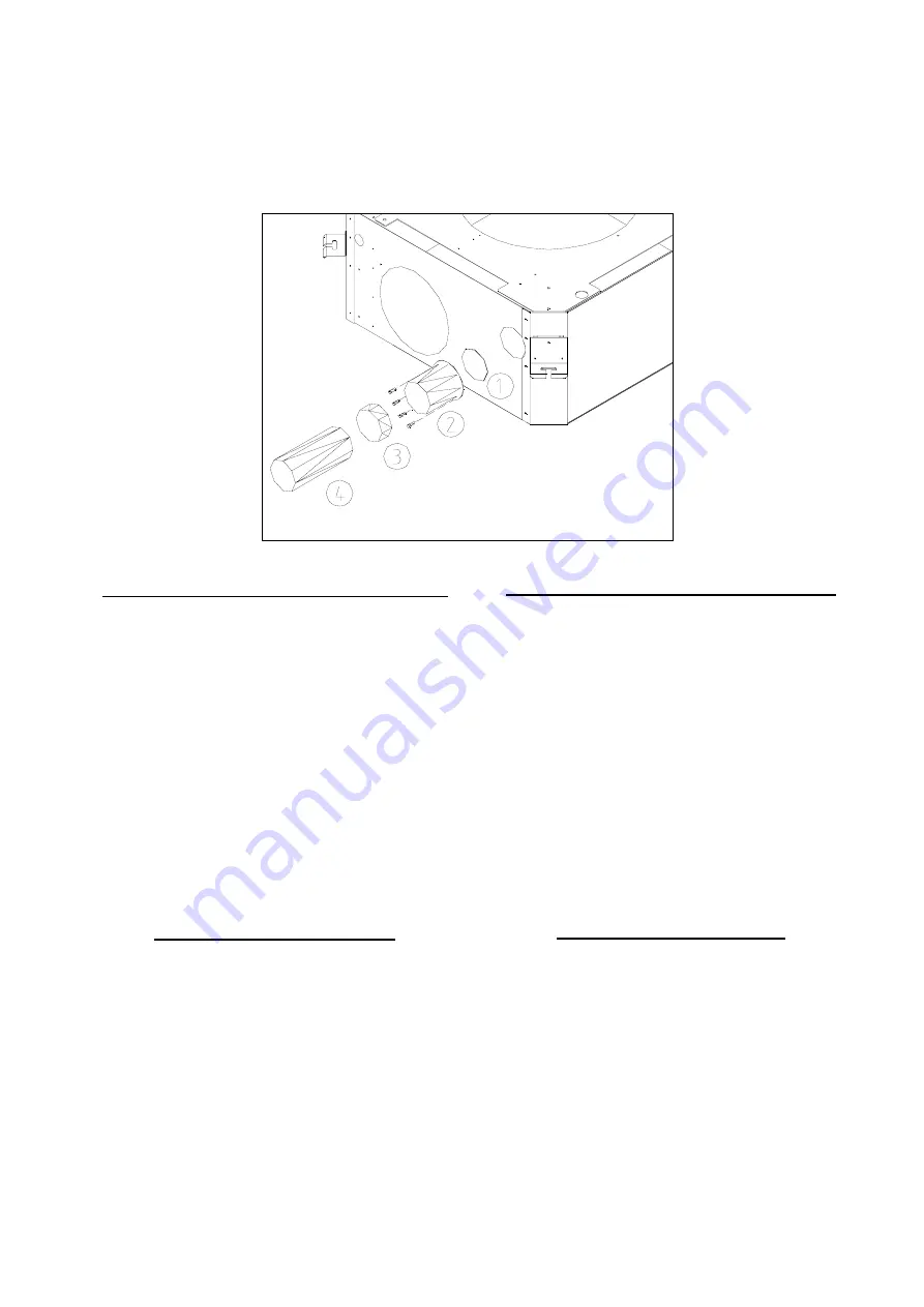
Descrizione schema montaggio condotto flessibile
Lamiera pretranciata da asportare
Raccordo imbocco e viti
Guarnizione
Condotto flessibile coibentato
L’eventuale ventilatore supplementare per
l’aspirazione dell’aria esterna (a cura dell’installatore)
deve essere collegato alla morsettiera come da
schemi allegati. Il funzionamento del ventilatore è in
parallelo alla valvola elettrotermica di regolazione, in
modo che si arresti alla chiusura della valvola.
Installare all’esterno una griglia di aspirazione con
telaio porta - filtro ispezionabile, per impedire
l’aspirazione di polvere e foglie che possono ostruire
irrimediabilmente la batteria di scambio termico
dell’unità.
Mandata aria in un locale attiguo
Togliere l’isolante interno anticondensa, avendo cura
di non danneggiare la batteria di scambio termico
retrostante.
Non è consentito utilizzare contemporaneamente le
due aperture laterali pretranciata per mandata aria in
un locale attiguo previste sull’unità
La mandata d’aria verso il locale attiguo richiede la
chiusura almeno della bocchetta corrispondente al
condotto. Tra il locale climatizzato (in cui è installata
l’unità) e quello attiguo, è necessario applicare una
griglia di ripresa aria, (possibilmente vicino al
pavimento) o in alternativa prevedere una porta con
un griglia che permette uno scambio d’aria tra i due
locali.
The ducts could be in polyester flexible type (with
steel spiral core) or in wrinkled aluminum, eternally
covered with anti condensate material (fiber glass
12±25 mm thick).
Once the installation is
over the surfaces that
have not been insulated
can be coated with anti
insulator condensate
(i.g.: expanded
neoprene, 6 mm thick).
Failure to comply with
these instructions can
cause drippings due to
the condensate; cannot
be held responsible for
possible damages.
Description of diagram assemblage flexible duct
Knockout plenum to remove
Connection entrance and screws
Gasket
Flexible duct covers
The additional fan for aspiration of external air
(installer’s responsability) must be connected to the
clamps as per enclosed diagrams. The operation of
the fan is in parallel to the register, so that it halts to
the closing of valve.
Install on the outside an air inlet grille with a
carry - filter loom that could be inspected, to prevent
the aspiration of dust and leaves that could obstruct
the unit heat exchanger.
Air supply to an adjacent room
Remove the inner anti condensate insulator, taking
care not to damage the behind thermic exchange coil.
It is not allowed to use simultaneously the two
opening sides prepunched for air ducting to an
adiacent room
The air supply to an adjacent room requires the
closing of at least the corresponding mouthpiece to
the duct. Between the conditioned place (in which it is
installed the unit) and the nearby one, it is necessary
to apply an air inlet grille, (possibly near to the floor) or
in alternative to foresee a door with a grate that allows
an air exchange between the two places.


