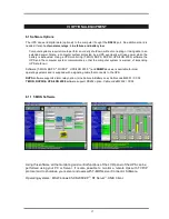
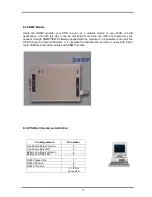
background image


18


6.2 SNMP Module 
 
Using  the  SNMP  module,  your  UPS  is  seen  as  a  network  device  in  your  WAN  or  LAN 
applications,  and  with  this  way  it  can  be  monitored  more  than  one  UPS’s  connected  to  your 
network through SNMPVIEW Software supplied with the module or it is possible to monitor the 
UPS  through  an  Internet  Browser.  It  is  possible  to  shutdown  the  servers  or  users  with  Client 
mate Software that communicates with SNMP module. 


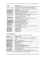
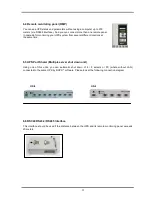
6.3 UPS DB-9 (female) port definition :  


Pin assignments 

Pin number 

Line Failure Relay Common 

Line Failure Relay NO 

Battery Low Relay Common 

Battery Low Relay NO 


RS232 Signal Gnd 

RS232 Receive 

RS232 Transmit 


1, 3, 8 Not 

Connected 


Содержание HP-115

Страница 1: ...USER MANUAL HP 100 SERIES UNINTERRUPTIBLE POWER SUPPLIES 1 Phase Input Output HP 115 NS151A ...

Страница 2: ......

Страница 3: ...ND Menu items 11 5 3 2 MEASURES Menu items 12 5 3 3 ALARMS Menu items 12 5 3 4 USER OPTIONS Menu items 13 5 3 5 TIME Menu items 14 5 3 6 CALIBRATION Menu items 14 5 3 7 ADJUST MODE submenu 14 5 3 8 INFORMATION Menu items 14 5 4 Fault messages and quick troubleshooting 15 5 5 STATUS Messages 16 VI OPTIONAL EQUIPMENT 17 6 1 Software Options 17 6 1 1 T MON Software 17 6 2 SNMP Module 18 6 3 UPS DB 9 ...

Страница 4: ......

Страница 5: ...rsonnel The output may be energized when the unit is not connected to a mains supply Risk of electric shock hazardous live parts inside this unit are energized from the battery supply even when the input AC power is connected To reduce the risk of electric shock disconnect the UPS from the mains supply before installing a computer interface signal cable Reconnect the power cord only after signalli...

Страница 6: ...testing optional High quality maintenance free lead acid type batteries High nonlinear load capacity special for computers Accessories o Optional UPS monitoring software T MON RUPS RUPSII UPSILON 2000 SNMP devices compatible to any operating system o Remote Monitoring Panel RMP available You can observe the UPS status and parameters without using a computer at a remote location up to 200 meters aw...

Страница 7: ...troller board In case of inverter overload or any other faults STS transfers the critical load to the mains without any interruption Mechanical Transfer Switch Opsiyonel The mechanical transfer switch consists of a manually operated switch When the UPS is switched off due to failure or maintenance it feeds critical loads from mains Battery Group It keeps dc voltage which is necessary for the inver...

Страница 8: ... 230 VAC Output Voltage Tolerance 1 Output Frequency 50 Hz Line Synchronized 1 Output Frequency Tolerance Free Running 0 2 Efficiency 100 Load 85 87 Crest Factor 3 1 Overload capacity 100 125 Load 2 5 min 125 150 Load 10 sec 150 instant by pass Total Harmonic Distortion THD 3 BATTERY Batteries 20x12V Floating Charge Voltage 270 Vdc End of Discharge Voltage 200 Vdc Autonomy Time 100 Load 10 min Cha...

Страница 9: ...5 Front View D H W Figure 2 2 Rear View RS232 and Alarm Contact Outputs PK1 On Off Switch F1 AC Input Fuse AC Output Connections F2 Batt Fuse F3 Batt Fuse ...

Страница 10: ...ftware T MON 3 2 Location Selection The UPS is designed to be installed in a protected environment The following conditions should be prohibited 1 Blocking the airflow intake and outlet It is recommended to retain 10 cm 4 minimum Between the rear side and the wall 2 Environment temperature and humidity out of specification 3 Location subject to excessive moisture dust and corrosion 4 Location expo...

Страница 11: ...on It is recommended that the UPS should be connected to the line voltage protected by a circuit breaker 1 Before connecting AC and DC power to the UPS make sure that the On Off Switch PK1 and Main Switch on the rear panel are in the 0 position OFF 2 Connect the AC and or DC input power to the UPS according to the label on the rear panel Perform the load connections according to the same label too...

Страница 12: ...rmittently Now the output receptacles are supplied from the battery source 4 Connect the power again and see that LINE FAILURE alarm is off 5 Now your UPS is ready to operate Plug in the critical loads to the output receptacles of the unit NOTE If any condition is different from the above situation call our local service representative for assistance CAUTION After initial start up keep power conti...

Страница 13: ...alarm and LINE FAILURE indicator on LCD panel will start operating 1 minute after the power is interrupted and you will see the message BAT USED 001min on the LCD panel This will show you for how long the batteries were used since the power was interrupted When the Battery Low alarm appears you have to shut down all your loads immediately and turn the main switch PK1 to position 0 4 4 Automatic ba...

Страница 14: ...f lamp is lit inverter supplies the load There are 3 function keys on front panel these are ENTER DOWN and DOWN keys help moving on menus key selects options ENTER key means the selected option or menu is valid NOTE During parameter settings sign will change into sign if button is pressed for 3 seconds and the parameter values will start decreasing 5 2 Front Panel Menu Descriptions By using menu b...

Страница 15: ...on SOUND ON Used for turning on off alert sound If you press ENTER key the option will change one press ON one press OFF If the OFF option is selected sound alert is turned off but if a new alarm UPS changes the option to ON state ENTER BYPASS If you press ENTER for 3 seconds the load is transferred to BYPASS automatically and the submenu item changes to ENTER INVERTER this time If you press ENTER...

Страница 16: ...UPS can be monitored via this menu navigation through the items is performed using up and down buttons Submenu item Function LOAD Output load percentage OP CURR A Output current OUTPUT 000 V Output voltage IPV 000 V 3 Phase input voltages BATTERY V Battery voltage BYPASS V By pass voltage FR HZ Input frequency Output frequency TEMP 000 C NORM UPS Internal temperature BAT TIME min Battery time ENTE...

Страница 17: ... start again battery trip out is off press ENTER for 3 seconds and then the selection is valid REMOTE OFF By using key you can change enable and disable options ON remote battery test shutdown and bypass functions are enabled OFF these functions are disabled press ENTER for 3 seconds and then the selection is valid LANG ENGLISH Turkish English is selected BOOST TIME HR Quick charge period of 1 15 ...

Страница 18: ...ed to adjust time and date of the UPS Submenu item Function Password required System adjustments ENTER EXIT Enter exit from submenu 5 3 7 ADJUST MODE submenu This menu is used to adjust time and date of the UPS Submenu item Function Password required System adjustments ENTER EXIT Enter exit from submenu 5 3 8 INFORMATION Menu items This menu gives information about the UPS Submenu item Function CO...

Страница 19: ...nlets 4 Bad UPS settling There is not enough ventilation area A12 OVERCURRENT Inverter output system failure 1 Internal overcurrent 2 Short circuit 3 UPS failure Call the service A13 OUTPUT LOW Inverter output voltage is below the min tolerated value Inverter is stopped A14 BATTERY HIGH Battery voltage is over than max tolerated value If the mains is off the tolerance when switching into bypass Th...

Страница 20: ...om USER OPTION MENU Press ENTER button for 3 seconds after mode selection then restart the UPS A24 P FAILURE 10 RS485 failure A25 PAR PSP FAIL Power supply error in parallel controller board A26 4 CABLE FAIL Master Slave digital cable connection error A27 P FAILURE 13 Parallel controller board failure online UPS found in parallel system A28 PLUG IN DIG Digital connection cable plug in failure A31 ...

Страница 21: ...at the computer system is warned of impending UPS shutdown Software T MON RUPS RUPSII UPSILON 2000 and SNMP devices is available for most operating systems and is supplied with a signaling cable that connects to the UPS RUPS software supports alarm relay option Line Failure Battery Low Cable code M2501 CC04 T MON RUPSII UPSILON 2000 software support RS232 option Cable code M2502 CC05 6 1 1 T MON S...

Страница 22: ...d with the module or it is possible to monitor the UPS through an Internet Browser It is possible to shutdown the servers or users with Client mate Software that communicates with SNMP module 6 3 UPS DB 9 female port definition Pin assignments Pin number Line Failure Relay Common 4 Line Failure Relay NO 2 Battery Low Relay Common 4 Battery Low Relay NO 5 RS232 Signal Gnd 7 RS232 Receive 6 RS232 Tr...

Страница 23: ...several different locations at the same time 6 5 UPS Port Sharer Multiple server shut down unit Using one of this units you can automatic shut down of 4 8 servers or PC where without LAN connected to the same UPS by RUPS software Please look at the following connection diagram US 8 US 4 6 6 RSC24 RS232 RS485 Interface This interface should be used if the distance between the UPS and its remote mon...

Страница 24: ...20 ...

Страница 25: ...21 Connection Diagram Of The RMP COM1 T MON ...

Страница 26: ...authorized people In case of a persistent failure or problem properly turn off the unit first Then review the following check list Be prepared to answer the questions before calling the service 1 Did you follow the operation procedure Did it happen on installation 2 Is the on off switch PK1 on the rear panel turned to position 1 3 Is the utility power of the wall outlet correct 4 Did a power failu...

Страница 27: ...the product has been subjected to physical abuse improper installation unauthorized service or modification 2 The sole responsibility of corporation under this warranty shall be limited to the repair or replacement of the product at the sole discretion of corporation 3 If it becomes necessary to send a defecting unit to corporation the product should be shipped in its original carton or in suitabl...

Страница 28: ...AGKK8480 06 2009 ...

Отзывы: