Page 10
Installation and Safety Guidelines
English
Installation
pro.Bose.com
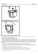
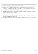
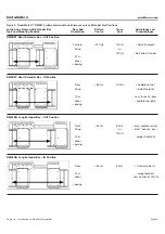
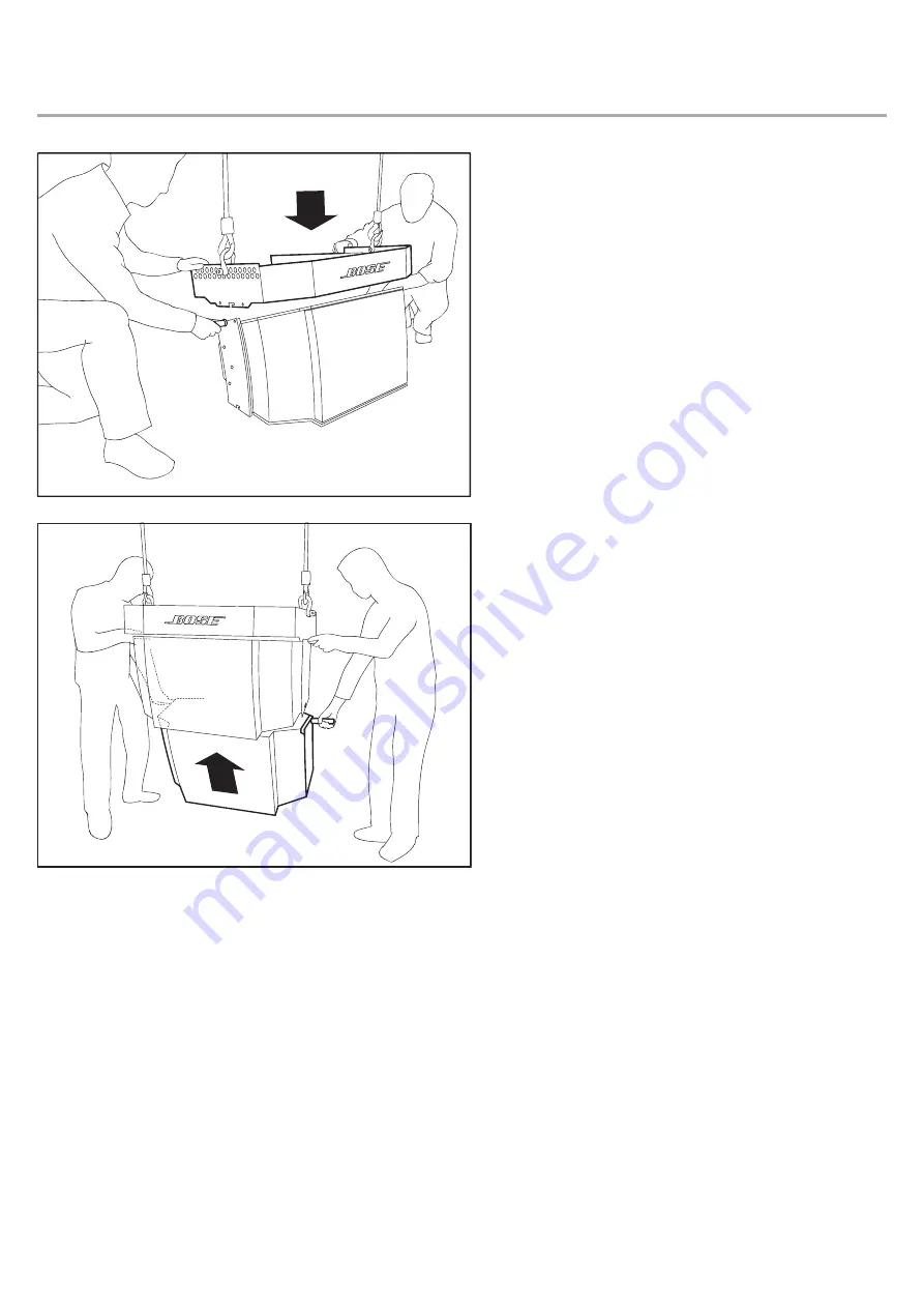
Figure 1. Positioning Frame on 1st Module
Figure 2. Attaching 2nd Module to 1st Module
For additional details on array configuration and installation, refer to the document
RoomMatch™ Array Design and Installation Manual
which is available for download at pro.Bose.com.
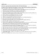
Section B: Pull Back Bracket on Bottom Module
The RMPULL pull-back bracket can be attached to the bottom module of an array to provide a third structural attachment point for
more extreme downward tilt than is possible with 2-point suspension. However, the Pull Back Bracket is not intended to provide primary
structural support for the entire array. The primary suspension points of the array frame should be as close as possible to the center of
gravity of the array to minimize the tension load in the pullback cable. Use the
RoomMatch™ Array Suspension Angle Calculator
soft-
ware to determine if the pull-back bracket is required and then to confirm that the pullback angle and working load is within acceptable
safe limits.
1.
In Section A above, follow steps 1 to 19 to assemble the array modules on the large or small array frame.
2.
With the tabs of the RMPULL bracket facing
downward
, align the 4 bolt holes of the tabs with the 4 bolt holes of the bottom
module sides plates. (Note: it may be helpful to use an alignment punch tool in the rear holes and then thread the bolts in the front
holes first.)
3.
Insert 4 bolts (2 per side) and finger tighten each until all bolts are installed.
4.
Tighten all 4 bolts with socket tool using torque of 35 to 40 foot-pounds (47 to 54 Newton-meters).
5.
Connect field wiring, test loudspeaker operation, and then elevate array assembly to final operating position.
6.
Adjust length of pullback cable attached to eyebolt of RMPULL bracket as required for desired array tilt angle.


