background image

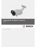
Integrated IR Bullet Camera

Safety | en       

7

14.

Refer all servicing to qualified service personnel. Servicing

is required when the apparatus has been damaged in a
way, such as power-supply cord or plug is damaged, liquid
has been spilled or objects have fallen into the apparatus,
the apparatus has been exposed to rain or moisture, does
not operate normally, or has been dropped.

1.3

Important Safety Instructions

CAUTION!

1. 

A regulated DC12V 1A power supply is recommended for
use with this camera for the best picture and the most
stable operation. An unregulated power supply can cause
damage to the camera. When unregulated power supply is
applied, product warranty will be out of subject.

2.

It is recommended that the camera is used with a monitor
that has a CCTV quality 75 Ohm video impedance level. If
your monitor is switched to high impedance then please
adjust accordingly.

3.

Do not attempt to disassemble the camera to gain access
to the internal compounds. Refer servicing to your dealer.

4.

Never face the camera towards the sun or any bright or

reflective light, which may cause smear on the picture and

possible damage to the CCD.

5.

Do not remove the serial sticker for the warranty service.

All-pole power switch -

 Incorporate an all-pole power switch,

with a contact separation of at least 3 mm in each pole, into the
electrical installation of the building. If it is needed to open the
housing for servicing and/or other activities, use this all-pole
switch as the main disconnect device for switching off the
voltage to the unit.

Camera grounding -

 For mounting the camera in potentially

damp environments, ensure to ground the system using the

ground connection of the power supply connector (see section:

Connecting external power supply).

Bosch Security Systems, Inc.

Installation Manual

| 1.0 | 2011.01

Содержание WZ18

Страница 1: ...en Installation Manual Integrated IR Bullet Camera WZ18 ...

Страница 2: ......

Страница 3: ...Important safety instructions 6 1 3 Important notices 7 1 4 Customer Support and Service 14 2 Features 16 3 Box Contents 17 4 Camera Parts and Adjustments 18 5 Installation 19 5 1 Mounting Position 19 5 2 Monitor Connection 20 6 Dimensions 21 7 Specifications 22 Bosch Security Systems Inc Installation Manual 1 0 2011 01 ...

Страница 4: ...8 4 Day Night Menu 24 8 5 Image Menu 24 8 6 3DNR Balance Menu 25 8 7 Special Menu 25 8 8 Reset Menu 25 8 9 OSD Function Description 26 8 9 1 Lens 26 8 9 2 Exposure 26 8 9 3 White Balance 27 8 9 4 Day and Night 27 8 9 5 Image 28 8 9 6 3DNR 28 8 9 7 Special 29 8 9 8 Reset 30 1 0 2011 01 Installation Manual Bosch Security Systems Inc ...

Страница 5: ... by the party responsible for compliance could void the user s authority to operate the equipment CAUTION These servicing instructions are for use by qualified service personnel only To reduce the risk of electric shock do not perform any servicing other than that contained in the operating instructions unless you are qualified to do so In USA and Canada use a Class 2 power supply only NOTICE Afte...

Страница 6: ...ng type plug has two blades and a third grounding prong The wide blade or the third prong is provided for your safety If the provided plug does not fit into your outlet consult an electrician for replacement of the obsolete outlet 10 Protect the power cord from being walked on or pinched particularly at plugs convenience receptacles and the power where they exit from the apparatus 11 Only use atta...

Страница 7: ...If your monitor is switched to high impedance then please adjust accordingly 3 Do not attempt to disassemble the camera to gain access to the internal compounds Refer servicing to your dealer 4 Never face the camera towards the sun or any bright or reflective light which may cause smear on the picture and possible damage to the CCD 5 Do not remove the serial sticker for the warranty service All po...

Страница 8: ...sconnecting the grounding plug or grounding terminal Follow proper safety precautions such as grounding for any outdoor device connected to this unit U S A models only Section 810 of the National Electrical Code ANSI NFPA No 70 provides information regarding proper grounding of the mount and supporting structure grounding of the coax to a discharge unit size of grounding conductors location of dis...

Страница 9: ...Moving Disconnect the power before moving the unit Move the unit with care Excessive force or shock may damage the unit and the hard disk drives Outdoor signals The installation for outdoor signals especially regarding clearance from power and lightning conductors and transient protection must be in accordance with NEC725 and NEC800 CEC Rule 16 224 and CEC Section 60 Permanently connected equipmen...

Страница 10: ...s only used to comply with safety standards or installation practices in certain countries Bosch does not recommend connecting system ground to safety ground unless it is explicitly required However if the system ground and safety ground are connected and grounding loops are causing interference in the video signal use an isolation transformer available separately from Bosch CAUTION Connecting Sys...

Страница 11: ... try to correct the interference by one or more of the following measures reorient or relocate the receiving antenna increase the separation between the equipment and receiver connect the equipment into an outlet on a circuit different from that to which the receiver is connected consult the dealer or an experienced radio TV technician for help Intentional or unintentional modifications not expres...

Страница 12: ...ccessivement hors et sous tension tout en contrôlant la réception radio ou télévision L utilisateur peut parvenir à éliminer les interférences éventuelles en prenant une ou plusieurs des mesures suivantes Modifier l orientation ou l emplacement de l antenne réceptrice Éloigner l appareil du récepteur Brancher l appareil sur une prise située sur un circuit différent de celui du récepteur Consulter ...

Страница 13: ...y of Bosch Security Systems and is protected by copyright All rights reserved Trademarks All hardware and software product names used in this document are likely to be registered trademarks and must be treated accordingly NOTE This manual has been compiled with great care and the information it contains has been thoroughly verified The text was complete and correct at the time of printing The ongo...

Страница 14: ...y sales us bosch com Technical Support Telephone 800 326 1450 Fax 585 223 3508 or 717 735 6560 E mail technical support us bosch com Canada Telephone 514 738 2434 Fax 514 738 8480 Europe Middle East Africa Region Repair Center Telephone 31 0 76 5721500 Fax 31 0 76 5721413 E mail RMADesk STService nl bosch com Asia Region Repair Center Telephone 65 63522776 Fax 65 63521776 E mail rmahelpdesk sg bos...

Страница 15: ... Warranty and more information For additional information and warranty queries please contact your Bosch Security Systems representative or visit our website at www boschsecurity com Bosch Security Systems Inc Installation Manual 1 0 2011 01 ...

Страница 16: ...on automatically switching between day color mode and night black white with IR modes Advanced digital video processing 10 bit image processing Digital Noise Reduction DNR for optimum night time images Privacy mask function allows blanking of specific areas of the scene Multi language On screen Display OSD control allowing camera configuration on the monitor screen Easy to install Mounting bracket...

Страница 17: ...t Camera Box Contents en 17 3 Box Contents WZ18 Bullet Camera Sunshield Video Output Test Cable L Wrench Screws 3 Sunshield Fixing Bolt Operation Manual this book Bosch Security Systems Inc Installation Manual 1 0 2011 01 ...

Страница 18: ... 4 Camera Parts and Adjustments 1 Sunshield Fixing Bolt 5 Photo cell 2 Sunshield 6 Body 3 Mounting Bracket 7 Body Fixing Ring 4 LEDs 20 8 External Zoom and Focus Adjustment External Zoom and Focus Controls 1 0 2011 01 Installation Manual Bosch Security Systems Inc ...

Страница 19: ...jury this apparatus must be securely attached to the floor wall in accordance with the installation instructions 360 90 360 CAUTION After adjusting the zoom and focus firmly tighten the zoom and focus lever to seal the camera against water ingress Bosch Security Systems Inc Installation Manual 1 0 2011 01 ...

Страница 20: ...UTION To prevent humidity problems the camera must be installed in dry conditions and the cable leads should be sealed once connected 1 DC 12V AC 24V 2 BNC Female 3 DC 12V AC 24V Power Supply 4 Video In 5 TV Monitor 1 0 2011 01 Installation Manual Bosch Security Systems Inc ...

Страница 21: ...Integrated IR Bullet Camera Dimensions en 21 6 Dimensions 82 87 8 120 224 130 M12 XP1 0 100 7 Ф65 mm in Bosch Security Systems Inc Installation Manual 1 0 2011 01 ...

Страница 22: ...4 X128 X256 Sense up Off Auto X2 X4 X8 X16 X32 X64 X128 X256 AGC Off Low Middle High BLC Off BLC HSBLC White Balance ATW PUSH PUSH LOCK MANUAL INDOOR OUTDOOR Day and NIght True Day and Night With ICR Mechanism Motion Detection Zone 4ea Mask On Off Privacy Zone Zone 8ea Mask On Off 3 DNR Off On 0 100 Level Adjustable D WDR Off Indoor Outdoor Image Freeze Mirror D zoom Sharpness Color gain Gamma NEG...

Страница 23: ...NR SPECIAL RESET EXIT 8 2 Exposure Menu LENS SHUTTER X256 1 100K EXPOSURE AGC LOW MIDDLE HIGH WHITE BAL SENSE UP X2 X256 GAIN LEFT RIGHT WIDTH TOP BOTTOM HEIGNT DAY NIGHT BLC BLC IMAGE HSBLC LEVEL LEFT RIGHT WIDTH TOP BOTTOM HEIGNT 3DNR D WDR INDOOR OUTDOOR SPECIAL RESET EXIT Bosch Security Systems Inc Installation Manual 1 0 2011 01 ...

Страница 24: ... Menu LENS EXPOSURE WHITE BAL DAY NIGHT AUTO D N LEVEL 0 3 IMAGE B W BURST ON OFF 3DNR COLOR SPECIAL RESET EXIT 8 5 Image Menu LENS FREEZE ON OFF EXPOSURE MIRROR MIRROR V FLIP ROATE WHITE BAL D ZOOM x1 x32 PAN 100 100 TILT 100 100 DAY NIGHT SHARPNESS 0 31 IMAGE COLOR GAIN BLUE 1 100 RED 1 100 3DNR GAMMA 0 05 1 SPECIAL NEG IMAGE ON OFF RESET EXIT 1 0 2011 01 Installation Manual Bosch Security Syste...

Страница 25: ...RUSSIAN GRRMAN DEUTSCH DUTCH WHITE BAL LEFT RIGHT DAY NIGHT MOTION ON OFF AREA SEL AREA DISPLAY WIDTH TOP BOTTOM IMAGE MOTION VIEW SENSITIVITY HEIGHT AREA 1 4 ON OFF 3DNR SPECIAL PRIVACY AREA SEL AREADISPLAY LEFT RIGHT WIDTH TOP BOTTOM RESET AREA 1 8 ON OFF COLOR HEIGHT EXIT SYNC INT 8 8 Reset Menu LENS EXPOSURE WHITE BAL DAY NIGHT IMAGE 3DNR SPECIAL RESET FACTORY RESET EXIT Bosch Security Systems...

Страница 26: ...Adjusts the Shutter Speed 1 60 50 1 250 1 500 1 2K 1 5K 1 10K 1 100K is for PAL TYPE BRIGHTNESS Adjusts the MANUAL Electronic Shutter value AGC Adjusts the Automatic Gain Control SENSE UP Low speed shutter control BLC Back Light Compensation HSBLC Highlight Suppression BLC darkens parts of the image to enhance the scene D WDR Dynamic wide Dynamic Range allows every detail to be captured accurately...

Страница 27: ... 5 400K 8 9 4 Day and Night Determines the switching moment between Color and B W mode DAY NIGHT AUTO D N LEVEL l 1 RETURN RET AUTO Sensor mode auto change Adjustable for variable D N change timing D N Level 1 Turn LED on with B W mode 4Lux Turn LED Off with Color Mode 7Lux The Higher D N Level turns into Black White mode at higher luminous intensity and vice versa The D N change timing could be a...

Страница 28: ...eversed LEFT and RIGHT image V FLIP Sets vertically flipped video ROTATION Sets rotation up to 180 degrees D ZOOM Expands one part of the monitor screen for viewing SHARPNESS Sets sharpness control COLOR GAIN Sets the RED GAIN or BLUE GAIN GAMMA Sets compensation according to the gamma value NEG IMAGE Sets negative image ON OFF 8 9 6 3DNR Sets three dimensional noise reduction LEVEL Sets noise red...

Страница 29: ...he width in the selected area TOP BOTTOM Sets TOP BOTTOM position in the selected area HEIGHT Sets the height in the selected area SENSITIVITY Sets the movement detection threshold value MOTION VIEW Displays the motion area on the screen PRIVACY Masks user defined areas of the view AREA SELECT Select the mask area from 1 to 8 AREA DISPLAY Toggle mask ON OFF in selected area LEFT RIGHT Sets LEFT RI...

Страница 30: ...30 en OSD Manual Integrated IR Bullet Camera 8 9 8 Reset Resets all settings to the factory default RESET FACTORY RESET RETURN RET 1 0 2011 01 Installation Manual Bosch Security Systems Inc ...

Страница 31: ......

Страница 32: ...Bosch Security Systems Inc 850 Greenfield Road Lancaster PA 17601 U S A www boschsecurity com Bosch Security Systems Inc 2011 ...

Отзывы: