background image

R

R

R

E

E

E

P

P

P

A

A

A

I

I

I

R

R

R


I

I

I

N

N

N

S

S

S

T

T

T

R

R

R

U

U

U

C

C

C

T

T

T

I

I

I

O

O

O

N

N

N


Washer-Dryer 

1


INTRODUCTION........................................... 2


1.1


Purpose of the document................................................... 2


1.2


General symbols ................................................................. 2


1.3


Safety-relevant symbols..................................................... 2


2


SAFETY ........................................................ 3


2.1


Qualifications of service technicians ................................ 3


2.2


Identification of danger levels ........................................... 3


2.3


Identification of damage to property ................................. 3


2.4


General safety instructions................................................ 4


3


CONSTRUCTION AND FUNCTION ............. 6


3.1


Operation ............................................................................. 6


3.2


Imbalance detection function ............................................ 8


3.3


Drying cycle......................................................................... 9


3.4


Dryer heater....................................................................... 10


3.5


Warm spin cycle................................................................ 11


3.6


NTC tasks .......................................................................... 12


3.7


Power module ................................................................... 15


4


DIAGNOSTICS ........................................... 17


4.1


Malfunctions...................................................................... 17


4.2


Mechanical faults .............................................................. 19


4.3


Result faults ...................................................................... 19


4.4


Noises ................................................................................ 19


4.5


Odours ............................................................................... 20


5


TEST AND REPAIR ....................................21


5.1


Connecting the appliance ................................................ 21


5.2


Removing door collar....................................................... 23


5.3


Removing the front panel ................................................ 24


5.4


Removing the pump ......................................................... 24


5.5


Removing dispenser tray housing .................................. 25


5.6


Removing the fan.............................................................. 26


5.7


Removing the dryer heater .............................................. 28


5.8


Removing the condenser ................................................. 29


5.9


Renewing the washing agitator ....................................... 31


5.10


Removing the float switch ............................................... 32


815_58300000146136_ara_en_b.doc – 12.04.10 

Seite 1 von 32 

Содержание WKD28350GB Installation Instructions, Instructions for Use, Programme Table

Страница 1: ...ce detection function 8 3 3 Drying cycle 9 3 4 Dryer heater 10 3 5 Warm spin cycle 11 3 6 NTC tasks 12 3 7 Power module 15 4 DIAGNOSTICS 17 4 1 Malfunctions 17 4 2 Mechanical faults 19 4 3 Result faults 19 4 4 Noises 19 4 5 Odours 20 5 TEST AND REPAIR 21 5 1 Connecting the appliance 21 5 2 Removing door collar 23 5 3 Removing the front panel 24 5 4 Removing the pump 24 5 5 Removing dispenser tray ...

Страница 2: ...he repair instructions the service technician uses the following documents Parts list Exploded drawing Circuit diagrams The described troubleshooting and repair may be carried out a service technician only These repair instructions are assigned to specific appliances and are valid for those appliances only 1 2 General symbols Symbol Meaning Special information 1 3 Safety relevant symbols Symbol Me...

Страница 3: ...ained by an electrical engineer on the work assigned to him and the potential hazards of improper behaviour and who was instructed on the required protective devices and protective measures Observe country specific regulations 2 2 Identification of danger levels Identification Meaning DANGER Imminent danger which may result in death or serious injury if it is not avoided WARNING Potentially immine...

Страница 4: ...ock Disconnect the appliance from the power supply Do not touch housing frame or components Use residual current operated circuit breaker if tests have to be conducted while the appliance is live Ensure that the resistance of the protective conductor does not exceed the standardised values WARNING Exposed conductive parts may be live if a fault has occurred Danger to life caused by electric shock ...

Страница 5: ... electrical discharge Observe measures to protect the components suscep tible to electrical discharge NOTE Components which are replaced haphazardly will be damaged beyond repair Before replacing components perform troubleshooting Check systematically Observe Technical Documentation Do not replace components without reason 815_58300000146136_ara_en_b doc 12 04 10 Seite 5 von 32 ...

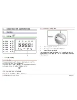
Страница 6: ...lly by the washer dryer and by the Fluff Clean symbol Fluff Clean is indicated on the display The symbol is lit until the programme has started 3 1 1 2 Running the programme 1 Drum empty and door closed 2 Move porgramme selector to Fluff Clean 3 Press Start Pause button The programme can also be run at any time without a request from the appliance It is recommended to run the programme approx ever...

Страница 7: ...cal washing action Childproof lock 3 1 2 1 Activation Simultaneously press the Option and Set Select buttons When the childproof lock is activated the key symbol is lit on the display 3 1 2 2 Deactivation Simultaneously press the Option and Set Select buttons for 3 s Attention When the appliance is switched off the childproof lock is deactivated 815_58300000146136_ara_en_b doc 12 04 10 Seite 7 von...

Страница 8: ...pin cycle 3 2 2 Appliances running at 800 1600 rpm Level Imbalance in kg Attempts Speed Cotton Level 0 U 0 65 0 05 Max speed Level 1 0 65 U 0 95 2 1000 rpm Level 2 0 95 U 1 15 2 600 rpm Level 3 U 1 15 2 No spin cycle Wool Level 0 U 0 95 Max speed Level 1 0 95 U 1 40 4 600 rpm Level 3 U 1 40 2 No spin cycle Measuring tolerances of the electronics 50 g Total tolerance of the appliance mech and elect...

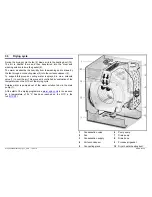
Страница 9: ...a a solenoid valve 1 to cool the air This process is controlled by evaluation of the temperatures on the NTCs of the drying cycle Surplus water is pumped out of the water solution tub via the drain pump 7 At the start of the drying programme a warm spin cycle is run as soon as a temperature of 54 C has been reached on the NTC in the tub NTCD1 815_58300000146136_ara_en_b doc 12 04 10 Seite 9 von 32...

Страница 10: ...Resistance measurement Connections Resistance in ohm 1 2 104 124 1 3 52 62 1 4 52 62 2 3 52 62 2 4 52 62 3 4 0 3 4 3 Function The temperature is controlled by an NTC at the inlet to the gasket Cottons coloureds 87 C 90 C Easy care 67 C 70 C Safety temperature 105 C Î error message In addition a resettable safety temperature controller monitors the maximum permitted temperature 150 C During the war...

Страница 11: ...fter the predrying cycle and when a temperature of 54 C has been reached on the NTC at the tub NTCD1 Drying programme Predry Warm spin Dry Cool down During the warm spin cycle the drum is first reversed at 54 rpm then the washing is spun up to max speed At the same time only one heating element is actuated 815_58300000146136_ara_en_b doc 12 04 10 Seite 11 von 32 ...

Страница 12: ...n cycle until the water temperature 60 C max filling time 3 is reached If T 60 C is not reached within 3 only the drain cycle is run Water temperature NTC 60 C N1 If the user stops the wash programme and selects Rinse Spin a cool down is run before the programme starts until T 60 C max filling time 3 is reached 1 NTC dryer heater NTCD3 4 NTC water heater 2 NTC condenser outlet NTCD2 5 NTC washing ...

Страница 13: ...out warm spin cycle Temperature NTC water heater 50 C If the user stops the drying programme and selects Drain Spin or Drain a cool down is run before the drain cycle until the air temperature NTC 45 C is reached If NTC 45 C is not reached within 10 only the drain cycle is run Air temperature NTCD1 68 C N0 If the user stops the drying programme and selects Drain Spin or Drain a cool down is run be...

Страница 14: ...ns Coloureds 90 C Easy care 70 C Excess temperature 105 C 3 6 2 4 Safety temperature switch 3 The safety temperature switch limits the temperature in the heating duct to 150 C if the NTCD3 1 is defective characteristic shifted It can be manually reset 815_58300000146136_ara_en_b doc 12 04 10 Seite 14 von 32 ...

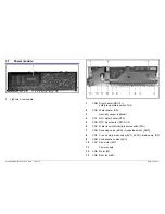
Страница 15: ...TC water heater NTC 5 CND NTC dryer heater NTCD1 3 6 CNC Water level controller pressure switch PRL 7 CNH Aquastop valve EAQ Aquastop switch AQS 8 CNF Pre and main wash valve EVC EVW drain pump DP 9 CNG Condensation valve EVC 10 CNV Fan motor MV 11 Power supply 12 CNE Motor M 13 CNB Door lock BP 815_58300000146136_ara_en_b doc 12 04 10 Seite 15 von 32 ...

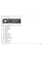
Страница 16: ...7 Motor M 7 Buzzer 8 TR10 Aquastop EAQ 9 TR8 Hot water valve EVH 10 TR6 Drain pump DP 11 TR3 Prewash valve EVP 12 TR2 Main wash valve EVW 13 TR1 Condensate valve EVC 14 TR11 Fan MV 15 R2 Motor M reversing 16 R7 Door lock BP 17 R1 Motor M tapping 815_58300000146136_ara_en_b doc 12 04 10 Seite 16 von 32 ...

Страница 17: ...red replace No spin cycle No draining pump or drainage hose blocked Clean pump and drainage hose No draining pump defective Replace pump Drive belt worn Attach drive belt and check motor belt pulley attachment and alignment of the appliance Drive belt torn Attach drive belt and check motor belt pulley attachment Fluff formation after drying in the door area During the drying cycle more or less flu...

Страница 18: ...ts Drain Spin or Drain Rinse Spin programme is not run Water temperature NTC 60 C N1 Before the programme starts cool down is run until the water temperature 60 C is reached max filling time 3 This may occur if the user stops the wash programme and selects Rinse Spin Air temperature NTCD1 68 C N0 Before the programme starts a cool down is run until the air temperature NTCD1 60 C is reached max fil...

Страница 19: ...m with a nylon socking Fault Cause Fault correction Advise customer Washing too wet after drying programme Imbalance therefore poor dehumidification due to spin termination drying capacity inadequate Advise the customer Spin washing before drying Combine large and small items of washing Fault Cause Fault correction Advise customer Clicking or banging noises Shock absorbers or suspension of the was...

Страница 20: ... out Check heater if required replace Check safety temperature controller if required replace Check heater NTC if required replace Fusty odour Drain hose blocked Check pump and drain hose if required clean Waste water connection siphon blocked Check waste water connection siphon and advise customer 815_58300000146136_ara_en_b doc 12 04 10 Seite 20 von 32 ...

Страница 21: ...595 cm x depth 584 cm x height 820 cm Weight 85 kg 5 1 3 Water supply The water connection inch requires a conventional water line with a water pressure between 50 900 kPa 0 5 9 bar When the tap is turned on the water flow rate must be more than 8 l min If the water pressure is higher a pressure reducing valve must be used Tighten plastic screw connections by hand only 5 1 4 Aqua Stop version opti...

Страница 22: ...50 cm 3 approx 135 cm 6 approx 95 cm 5 1 7 Electrical connection Connect the appliance to a correctly installed earthed socket only Comply with the specifications on the rating plate Do not use multiple connectors couplings or extension cables Fuse 10 A 815_58300000146136_ara_en_b doc 12 04 10 Seite 22 von 32 ...

Страница 23: ...ollar from front panel 7 Remove door lock 8 Remove front panel 9 Remove connecting piece from the heating duct 1 Loosen screw remove clamp 2 Remove gasket 10 Detach rear clamping ring 1 Flexible extension 340852 2 Bit adapter 340869 3 Torx bit TX20 11 Detach gasket 5 2 3 Installation To facilitate installation coat the joint with washing up liquid 815_58300000146136_ara_en_b doc 12 04 10 Seite 23 ...

Страница 24: ...el forwards out of the retaining pins 5 4 Removing the pump To remove the pump it is not necessary to remove the appliance The drain pump can be removed from the front by removing the front panel CAUTION Risk of being cut Sharp edges Wear gloves The pump is attached at the front with two screws Further access is possible via the base plate 815_58300000146136_ara_en_b doc 12 04 10 Seite 24 von 32 ...

Страница 25: ...front panel 3 Remove plastic lug 4 Remove VDE cover 5 Remove hose connections 6 Remove cross bar 7 Loosen screws on the valve block 8 Loosen cable connections 1 Cross bar 2 Cable connections 3 Valve block screws 815_58300000146136_ara_en_b doc 12 04 10 Seite 25 von 32 ...

Страница 26: ...fety pin 1 Torx 20 with safety pin 3 Remove back cross bar 4 To do this detach hose connections and electrical connections The cross bar cannot be removed backwards until all screws have been loosened 5 Remove upper cross bar 6 Remove heating duct cover 7 Remove the fan 1 Back cross bar 2 Upper cross bar 3 Heating duct cover 4 Fan 815_58300000146136_ara_en_b doc 12 04 10 Seite 26 von 32 ...

Страница 27: ... 2 Installation Renew the seals 5 and 6 if required If required also seal with heat resistant silicone 5 Fan sealing tape 6 Fan heater sealing tape 815_58300000146136_ara_en_b doc 12 04 10 Seite 27 von 32 ...

Страница 28: ...subsequent installation 1 RD1 Î CNM3 2 RD2 Î CNM1 3 RD1 Î THS RD2 4 RD2 Î THS RD1 5 Remove heater holder 5 7 2 Installation 1 Renew seals 2 Install heater with heater holder 3 Connect cable connections Ensure the plug in connections are connected correctly 4 Attach heating duct cover 5 Attach upper cross bar 6 Attach VDE cover 815_58300000146136_ara_en_b doc 12 04 10 Seite 28 von 32 ...

Страница 29: ...ross bar 5 Remove screws 1 from housing 1 Screws 1 Support rail 2 Condenser clamping ring 3 Washing machine tub clamping ring 4 Screw for support rail 6 Remove clamping ring from washing machine tub 3 7 Remove screw 4 from the support rail 1 8 Place support rail down 9 Remove condenser downwards 815_58300000146136_ara_en_b doc 12 04 10 Seite 29 von 32 ...

Страница 30: ... Leak Leakage water When installing the collar on the tub do not use any lubricant e g washing up liquid as the gasket can easily slip off the connecting piece again Ensure it is seated correctly 5 Attach back cross bar 6 Attach back appliance cover 7 Connect plug to NTC condenser output NTCD2 8 Attach VDE cover 815_58300000146136_ara_en_b doc 12 04 10 Seite 30 von 32 ...

Страница 31: ...ing a screwdriver 2 Pull washing agitator forwards out of its holder 5 9 2 Installation 1 Bend sheet metal bracket upwards 2 Insert washing agitator into guide grooves and push back wards until the sheet metal bracket engages 815_58300000146136_ara_en_b doc 12 04 10 Seite 31 von 32 ...

Страница 32: ...oving the float switch The float switch is attached to the base plate from below with two screws To remove the float switch the appliance must be tilted 815_58300000146136_ara_en_b doc 12 04 10 Seite 32 von 32 ...

Отзывы: