background image

Installation and User Guide | 

VIP X1/VIP X2

EN

 | 28

Configuration using a Web Browser

Bosch Security Systems | 2005-05 | V1.0

Beginning configuration

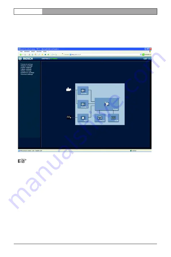
Click on the 

SETTINGS

 link in the upper section of the 

LIVEPAGE

 window. A 

new page containing the configuration menu (see 

Configuration menu

page 47) and the unit overview (see 

Unit overview

, page 29) is opened. 

Note

Depending on whether you are using a VIP X1 or a VIP X2, the screen 
display may differ slightly from that shown above.

Содержание VIP X1

Страница 1: ...VIP X1 VIP X2 Network video server ...

Страница 2: ... user guide has been compiled with great care and the information it contains has been thoroughly verified The text was complete and correct at the time of printing The ongoing development of the products may mean that the content of the user guide can change without notice Bosch Security Systems accepts no liability for damage resulting directly or indirectly from faults incompleteness or discrep...

Страница 3: ...stem requirements for setup 9 Configuration requirements 10 Operational requirements 10 Overview of functions 11 Front panel connections 14 Rear panel connections 15 Chapter 4 Installation Connections 18 Turning on off 20 Setup using a terminal program 21 Chapter 5 Configuration using a Web Browser Connecting 25 Choosing the configuration mode 27 Unit overview 29 Configuration menu 47 Function tes...

Страница 4: ... 84 Establishing the connection 84 Closing the connection 86 Operation with decoder software 87 Chapter 7 Maintenance and upgrades Testing the network connection 89 Device reset 89 Repairs 90 Transfer and disposal 90 Chapter 8 Appendix Troubleshooting 91 LEDs 93 Terminal block 94 Glossary 95 Specifications 97 Chapter 9 Index ...

Страница 5: ...owledge of network technology is required The user guide describes the installation and operation of the unit Conventions In this user guide the following symbols and notation are used to draw attention to special situations Warning This symbol indicates that failure to follow the safety instructions described may endanger persons and cause damage to the unit or other equipment It is associated wi...

Страница 6: ... of the units which are not answered in this manual please contact your sales partner or Bosch Sicherheitssyteme GmbH Robert Koch Straße 100 85521 Ottobrunn Germany www bosch sicherheitssysteme de EU Directives The VIP X1 and VIP X 2 network video servers comply with the requirements of EU Directives 89 336 Electromagnetic Compatibility and 73 23 amended by 93 68 Low Voltage Directive Rating plate...

Страница 7: ...vices Install the power supply and the unit only in dry weather protected areas If safe operation of the unit cannot be ensured remove it from service and secure it to prevent unauthorized start up Safe operation is no longer possible in the following cases if there is visible damage to the unit or power cables if the unit no longer works properly if the unit has been exposed to rain or moisture i...

Страница 8: ...h as cameras The documentation contains important safety instructions and information about permitted uses Perform only the installation and operating steps described in this manual Actions beyond these may lead to personal injury damage to property or damage to the equipment Maintenance and repair Never open the housing of the VIP X The unit does not contain any user serviceable parts Never open ...

Страница 9: ...e in English German Datasheet System Requirements MPEG ActiveX control MPEG viewer DirectX control Microsoft Internet Explorer Microsoft Virtual Machine Adobe Acrobat Reader Note Check that the delivery is complete and in perfect condition Arrange for the unit to be checked by Bosch Security Systems if you find any damage System requirements for setup Computer with Windows 2000 XP operating system...

Страница 10: ...be installed from the product CD provided see Components supplied page 9 Operational requirements Computer with Windows 2000 XP operating system network access and Microsoft Internet Explorer web browser version 6 0 or later or Computer with Windows 2000 XP operating system network access and reception software for example VIDOS or MPEG 4 compatible hardware decoder from Bosch Security Systems suc...

Страница 11: ...xample a VIP X as the transmitter and another VIP XD as the receiver can form a stand alone system for data transfer without a PC Video images from a single transmitter can be simultaneously received on several receivers Receiver MPEG 4 compatible hardware decoders for example VIP XD can be used as a receiver Computers with decoding software such as VIDOS or computers with the Microsoft Internet E...

Страница 12: ...l serial interface This interface can also be used to transmit transparent data Configuration The VIP X can be configured using a browser on the local network Intranet or from the Internet Similarly firmware updates and rapid loading ofdevice configurations are also possible Snapshots Individual video frames snapshots can be called up as JPEG images by the VIP X stored on the hard drive or display...

Страница 13: ...Two analog BNC video inputs FBAS PAL NTSC on the VIP X2 Video encoding using international MPEG 4 standard Integrated Ethernet interface 10 100 Base T Transparent bi directional data channel using a serial interface RS232 RS422 RS485 Remote control of all built in functions via TCP IP Password protection to prevent unauthorized connection or configuration changes Four relay inputs for external sen...

Страница 14: ...sch Security Systems 2005 05 V1 0 Front panel connections VIP X1 1 Video input Video In BNC jack for connection of video source VIP X2 2 Video input Video In 1 BNC jack for connection of video source 3 Video input Video In 2 BNC jack for connection of second video source ...

Страница 15: ...larm inputs relay output serial interface and power supply 7 Operating status LED flashes green when ready for operation 8 LED L lit green when the unit is connected to the network 9 LED T flashes orange when data is being transmitted over the network 10 RJ45 jack ETH for connecting to an Ethernet LAN local network 10 100 MBit Base T Further information on the LEDs can be found on page 93 Informat...

Страница 16: ...Installation and User Guide VIP X1 VIP X2 EN 16 Product description Bosch Security Systems 2005 05 V1 0 ...

Страница 17: ...ot exceed 80 The unit generates heat during operation Ensure that there is adequate ventilation and also that there is enough clearance between the unit and heat sensitive objects or equipment Please ensure the following conditions for installation Do not mount the unit close to heaters or other heat sources Avoid locations subject to direct sunlight Allow sufficient space for running cables Ensur...

Страница 18: ...e is made up of four terminals of the ST500 jack for pin assignment see page 94 The range of controllable devices is growing constantly The manufacturers of this equipment can provide specific information on installation and control Warning Refer to the device documentation when installing and operating a device to be controlled This contains important safety instructions and information about per...

Страница 19: ...o IN4 and check that the connection is secure Relay output The VIP X has a relay output for switching external devices such as lights or audible alarms This relay output can be activated manually during an active connection with the VIP X Moreover the output can be configured to activate audible alarms or other devices as a response to an alarm signal The relay output is also located on the orange...

Страница 20: ...to ensure that the mains supply is free of interference such as voltage surges spikes or voltage drops Warning Connect VIP X to the mains only after everything else has been connected Using the power supply unit cable connect the terminal block to the orange jack on the VIP X Ensure that the correct primary adapter is attached to the power supply unit and an appropriate mains socket is available P...

Страница 21: ...am disconnect the VIP X from the data network and disconnect the power supply unit from the mains socket Connect the open lines of the configuration cable with the terminal block that is already connected to the power supply unit The assignment can be seen from the labels on the configuration cable and the markings on the terminal block Connect the terminal block with the orange socket on the unit...

Страница 22: ...ly one command at a time After entering a value such as an IP address re check the entry before pressing the ENTER key to transfer the values to the VIP X Assigning an IP address To operate the VIP X in your network a network valid IP address must be assigned The following default addresses have been pre set at the factory 192 168 0 1 Start up a terminal program such as HyperTerminal Enter the use...

Страница 23: ...tings required Note The new IP address and a new subnet mask or gateway address will only be valid after restarting Restart Briefly disconnect the power supply to the VIP X disconnect power supply unit and re connect after a few seconds Additional parameters Using the terminal program you can check other basic parameters and modify them where necessary Use the on screen commands displayed in the v...

Страница 24: ...Installation and User Guide VIP X1 VIP X2 EN 24 Installation Bosch Security Systems 2005 05 V1 0 ...

Страница 25: ...d from the product CD provided see Components supplied page 9 Instructions for using the Web browser can be found in its online help System requirements Microsoft Internet Explorer version 6 0 or higher Monitor resolution 1024 768 pixels Network access Intranet or Internet Note You should also take note of the information in the System requirements datasheet on the product CD supplied Install MPEG...

Страница 26: ...the factory 192 168 0 1 Start the Web browser Enter the IP address of the VIP X as the URL The connection will be established and after a short time the LIVEPAGE with the video image will appear Note Depending on whether you are using a VIP X1 or a VIP X2 the screen display may differ slightly from that shown above If the connection is not established the maximum number of possible connections may...

Страница 27: ...t the desired page is displayed Choosing the configuration mode There are two options for configuring the VIP X or checking the current setup the unit overview or the configuration menu All settings are stored in the VIP X memory and they are preserved even if the power is interrupted Unit overview The unit overview shows the most important parameters summarized into six groups This allows you to ...

Страница 28: ...guration Click on the SETTINGS link in the upper section of the LIVEPAGE window A new page containing the configuration menu see Configuration menu page 47 and the unit overview see Unit overview page 29 is opened Note Depending on whether you are using a VIP X1 or a VIP X2 the screen display may differ slightly from that shown above ...

Страница 29: ...en Click in the text fields to enter values or use the other controls available such as buttons check boxes or list fields Click on the SETTINGS link at the top of the window to close the window without saving the changes made Making changes After making changes in a window click the Set button to send the new settings to the unit and save them there Warning Save the changes made in each window by...

Страница 30: ...ich you can select different compression settings for example one setting for transmissions to the Internet and one for LAN connections Note The settings must be made individually for each camera input and each stream The designations Video 1 and Video 2 on the VIP X2 corresponds to the labeling of the video inputs on the actual unit Pre programmed profiles are available each giving priority to di...

Страница 31: ...88 240 pixels Profile 7 Modem For analog modem connections at 20 kBit s resolution 352 x 288 240 pixels Profile 8 GSM For GSM connections at 9 600 baud resolution 176 x 144 120 pixels Active encoder profile Here you can select the desired profile for each of the two streams VIP X2 only First click on a tab to select the corresponding camera Click on a tab to select the associated stream Select the...

Страница 32: ...f you are completely familiar with all the configuration options Note The parameters as a group constitute a profile and are dependent on one another If you enter a setting outside the allowed range for a parameter the nearest valid value will be substituted when the settings are saved Profile name You can enter a new name for the profile here The name is then displayed in the list of available pr...

Страница 33: ...ween 4 and 31 on a slide bar The value 4 represents the best quality with if necessary a lower frame refresh rate depending on the settings for the maximum data rate A value of 31 results in a very high refresh rate and lower image quality I frame video quality This setting allows you to adjust the image quality of the I frames The Auto option automatically adjusts the quality to the settings for ...

Страница 34: ...esolution Here you can select the desired resolution for the MPEG 4 video image The following resolutions are available QCIF 176 144 120 pixels CIF 352 288 240 pixels 1 2 D1 352 576 480 pixels 2CIF 704 288 240 pixels D1 4CIF 704 576 480 pixels Reset of profile Click Default to return the profile to the factory default values ...

Страница 35: ...es in more extensive systems for example using the VIDOS software Note The unit name is used for remote identification of a unit in the event of an alarm for example Enter a name that makes it as easy as possible to identify the location unambiguously Unit ID Each VIP X should be assigned a unique identifier that can be entered here as an additional means of identification Password A VIP X is gene...

Страница 36: ...tions of the VIP X and change all configuration settings The user name user represents the middle authorisation level You can use it to operate the unit and also to control cameras but you cannot change the configuration The user name live represents the lowest authorization level It can only be used to view the live video image and switch between the different live image displays Password You can...

Страница 37: ...e a number of devices operating in your system or network it is important to synchronize their internal clocks For example it is only possible to carry out correct identification and evaluation of recordings occurring at the same time if all devices are operating on the same time Enter the current date Since the unit time is controlled by the internal clock it is not necessary to enter the day of ...

Страница 38: ...ersion information The hardware and firmware version numbers are for information only and cannot be altered Keep a record of these numbers in case technical assistance is required Hardware version The hardware version number of the VIP X is displayed Firmware version The firmware version number of the VIP X is displayed ...

Страница 39: ... external alarm sensor Otherwise select Off Select Active high if the alarm is to be triggered by closing the contact Select Active low if the alarm is to be triggered by opening the contact Name You can enter a name for each alarm input which is then displayed below the icon for the alarm input on the LIVEPAGE during configuration see Livepage configuration page 71 Video loss alarm Click the chec...

Страница 40: ...alarm Note For alarm connections always Stream 2 is transmitted Take this into account when assigning the profile see page 31 Number of destination IP address Here you assign the numbering for the IP addresses to be contacted in the event of an alarm The unit contacts the remote locations one after the other in the numbered sequence until a connection has been established Destination IP address Fo...

Страница 41: ... network Warning Changes to the IP address subnet mask or gateway address are transferred to the unit by clicking Set However they only take effect after the unit is restarted Click Set after entering a new IP address To do this enter the old IP address followed by reset for instance 192 168 0 80 reset in the address bar of your web browser The VIP X will be restarted after which it can only be ac...

Страница 42: ...st operation is only possible with the UDP protocol The TCP protocol does not support multicast connections Note The MTU value in UDP mode is 1514 bytes Ethernet link type If the VIP X is connected to the network via a switch both devices must have the same preset network connection type If necessary ask your network administrator what value the associated switch is set to Choose Auto for an autos...

Страница 43: ...associated tabs Note The prerequisite for multicast operation is a multicast capable network that uses the UDP and IGMP protocols Other group membership protocols are not supported The TCP protocol does not support multicast connections A special IP address class D address must be configured for multicast operation in a multicast enabled network The network must support group IP addresses and the ...

Страница 44: ...nnections for up to five simultaneously connected receivers Note Duplication of data places a heavy demand on the CPU and can lead to impairment of the image quality under certain circumstances Port If there are simultaneous data streams at the same multicast address you must assign different ports to each data stream Enter the port address for the relevant stream here Streaming Click in the check...

Страница 45: ...owever after about 15 seconds of inactivity the data connection is automatically terminated and another remote location can exchange transparent data with the unit Serial port function Select a controllable device from the list If you want to use the interface to transmit transparent data select Transparent To operate the unit with a terminal choose Terminal Note After selecting a device the remai...

Страница 46: ...owser Bosch Security Systems 2005 05 V1 0 Stop bits Select the number of stop bits per character Parity check Select the type of parity check Interface mode Select the desired protocol for the serial interface Half duplex mode Choose the setting appropriate for your application ...

Страница 47: ...e changed by entering new values or by selecting a predefined value in a list field Navigation You will see the configuration menu in addition to the unit overview after clicking on the SETTINGS link on the LIVEPAGE Click on one of the menu options on the left of the window The associated sub menu is opened Click one of the links in the sub menu The corresponding page will be opened Note Depending...

Страница 48: ...aves only the settings in the particular field Changes in any other fields are ignored Unit identification Unit name The unit can be assigned a name to assist in identifying it The name simplifies the management of multiple devices in more extensive systems for example using the VIDOS software Note The unit name is used for remote identification of a unit in the event of an alarm for example Enter...

Страница 49: ...ee user names service user and live which correspond to different authorization levels The user name service represents the highest authorisation level After entering the corresponding password you can use it to access all the functions of the VIP X and change all configuration settings The user name user represents the middle authorisation level You can use it to operate the unit and also to cont...

Страница 50: ... here Date and time Date format Choose the desired date format here Europe DD MM YYYY USA MM DD YYYY Japan YYYY MM DD Unit date and time If there are a number of devices operating in your system or network it is important to synchronize their internal clocks For example it is only possible to carry out correct identification and evaluation of recordings occurring at the same time if all devices ar...

Страница 51: ...ng daylight savings time if the time change is to be taken into account Deactivate the check box to switch to winter time Time server IP address Enter the IP address of a time server working with the RFC 868 protocol Camera names The camera name makes it easier to identify the remote camera location in the event of an alarm for example It will be displayed in the video screen if configured to do s...

Страница 52: ...ay of this information is to be shown Time stamping This field sets the position of the time and date overlay It can be displayed at the Top at the Bottom or at a position of your choice which you have pre defined using HyperTerminal using the Custom option Or it can be set to Off if no overlay of this information is to be shown Alarm mode stamping Choose On if a text message should be overlaid in...

Страница 53: ...ed Picture settings You can set the video image of each camera to suit your requirements The current video image is displayed in the small window next to the sliders as confirmation The changes take effect immediately First click on a tab to select the corresponding camera VIP X2 only Set the slide bar to the desired position Click Default to reset all settings to their default values Contrast 0 2...

Страница 54: ...ata streams Dual Streaming for each video input for which you can select different compression settings for example one setting for transmissions to the Internet and one for LAN connections Note The settings must be made individually for each camera input and each stream The designations Video 1 and Video 2 on the VIP X2 corresponds to the labeling of the video inputs on the actual unit Pre progra...

Страница 55: ... x 288 240 pixels Profile 7 Modem For analog modem connections at 20 kBit s resolution 352 x 288 240 pixels Profile 8 GSM For GSM connections at 9 600 baud resolution 176 x 144 120 pixels Active profile Here you can select the desired profile for each of the two streams VIP X2 only First click on a tab to select the corresponding camera Click on a tab to select the associated stream Select the des...

Страница 56: ...f you are completely familiar with all the configuration options Note The parameters as a group constitute a profile and are dependent on one another If you enter a setting outside the allowed range for a parameter the nearest valid value will be substituted when the settings are saved Profile name You can enter a new name for the profile here The name is then displayed in the list of available pr...

Страница 57: ...ween 4 and 31 on a slide bar The value 4 represents the best quality with if necessary a lower frame refresh rate depending on the settings for the maximum data rate A value of 31 results in a very high refresh rate and lower image quality I frame video quality This setting allows you to adjust the image quality of the I frames The Auto option automatically adjusts the quality to the settings for ...

Страница 58: ...esolution Here you can select the desired resolution for the MPEG 4 video image The following resolutions are available QCIF 176 144 120 pixels CIF 352 288 240 pixels 1 2 D1 352 576 480 pixels 2CIF 704 288 240 pixels D1 4CIF 704 576 480 pixels Reset of profile Click Default to return the profile to the factory default values ...

Страница 59: ...to the labeling of the video inputs on the actual unit VIP X2 only 75 Ohm termination Select Off if the video signal is to be transmitted Source type To allow the connection of video recorders as a video source you can change the video source characteristics from the default Camera to VCR Video recorders require a more tolerant setting for the internal PLL as a result of jitter effects caused by t...

Страница 60: ...elect Active high if the alarm is to be triggered by closing the contact Select Active low if the alarm is to be triggered by opening the contact Name You can enter a name for each alarm input which is then displayed below the icon for the alarm input on the LIVEPAGE during configuration see Livepage configuration page 71 Video loss alarm Click the check box if you want interruption of the video s...

Страница 61: ...re defined IP address in the event of an alarm Note For alarm connections always Stream 2 is transmitted Take this into account when assigning the profile see page 55 Number of destination IP address Here you assign the numbering for the IP addresses to be contacted in the event of an alarm The unit contacts the remote locations one after the other in the numbered sequence until a connection has b...

Страница 62: ...ted state of the relay is maintained In monostable operation the time can be selected after which the relay reverts to its idle state You can choose various events that activate the output automatically Thus for example it is possible to switch on a spotlight in response to a motion alarm and switch it off again when the alarm is over Idle state Select Open if the relay is to operate as a normally...

Страница 63: ... alarm Triggering caused by loss of the video signal Local input 1 Triggering by external alarm input 1 Remote input 1 Triggering by a relay contact at a remote location only when a connection is established Relay name The relay can be assigned a name here The name will be shown on the button next to Trigger relay The Livepage can also be configured to display the name next to the relay icon Trigg...

Страница 64: ... inactivity the data connection is automatically terminated and another remote location can exchange transparent data with the unit Serial port function Select a controllable device from the list If you want to use the interface to transmit transparent data select Transparent To operate the unit with a terminal choose Terminal Note After selecting a device the remaining parameters in the window ar...

Страница 65: ...osch Security Systems 2005 05 V1 0 Configuration using a Web Browser Parity check Select the type of parity check Interface mode Select the desired protocol for the serial interface Half duplex mode Choose the setting appropriate for your application ...

Страница 66: ... 192 168 0 80 reset in the address bar of your web browser The VIP X will be restarted after which it can only be accessed at the new IP address IP address Enter the desired IP address for the VIP X in this field The IP address must be valid for the network Subnet mask Enter the appropriate subnet mask for the set IP address here Gateway address If you want the unit to establish a connection to a ...

Страница 67: ...e VIP X is connected to the network via a switch both devices must have the same preset network connection type If necessary ask your network administrator what value the associated switch is set to Choose Auto for an autosensing network connection If necessary you can set the value to 10 or 100 MBit s for either full or half duplex mode FD or HD Warning Malfunctions can occur for example image fa...

Страница 68: ...associated tabs Note The prerequisite for multicast operation is a multicast capable network that uses the UDP and IGMP protocols Other group membership protocols are not supported The TCP protocol does not support multicast connections A special IP address class D address must be configured for multicast operation in a multicast enabled network The network must support group IP addresses and the ...

Страница 69: ...nnections for up to five simultaneously connected receivers Note Duplication of data places a heavy demand on the CPU and can lead to impairment of the image quality under certain circumstances Port If there are simultaneous data streams at the same multicast address you must assign different ports to each data stream Enter the port address for the relevant stream here Streaming Click in the check...

Страница 70: ...ersion information The hardware and firmware version numbers are for information only and cannot be altered Keep a record of these numbers in case technical assistance is required Hardware version The hardware version number of the VIP X is displayed Firmware version The firmware version number of the VIP X is displayed ...

Страница 71: ...ust correspond to the access mode for example C Images Logo gif for access to local files or http www mycompany com images logo gif for access via the Internet Intranet For access via the Internet Intranet there must be a connection in order to display the image The image files are not stored on the VIP X Mark the checkboxes for the information to be displayed on the LIVEPAGE The selected elements...

Страница 72: ...ding icon changes color Show event log The event messages will be displayed with the date and time in a field next to the video image Show system log The system messages will be displayed with the date and time in a field next to the video image and provide information about the establishment and termination of connections etc Save event log Select this option to save event messages in a text file...

Страница 73: ...r File for system log Enter the path for saving the system log here If necessary click Search to find a suitable folder Path for JPEG and MPEG files Enter the path for the storage location of individual images and video sequences that you can save from the LIVEPAGE If necessary click Search to find a suitable folder ...

Страница 74: ... correct upload file Uploading the wrong files can result in the unit no longer being addressable requiring it to be replaced Do not interrupt the firmware installation for any reason Interruption will result in incorrect programming of the Flash EPROM This can result in the unit no longer being addressable requiring it to be replaced First save the update file to the hard disk Enter the full path...

Страница 75: ... A dialog will appear Follow the instructions to save the current settings Configuration upload Enter the full path of the file to upload or click Browse to select the desired file Make certain that the file to be loaded comes from the same device type as the unit you want to reconfigure Click Upload to begin transmission to the unit The progress bar allows you to monitor the transfer Once the upl...

Страница 76: ...uld check that it works properly after installation and configuration This is the only way to ensure that the VIP X will function as intended in the event of an alarm Your check should include the following functions Can the VIP X be called remotely Does the VIP X transmit all the data required Does the VIP X respond as desired to alarm events Is it possible to control peripheral devices if necess...

Страница 77: ...age 9 Instructions for using the Web browser can be found in its online help System requirements Microsoft Internet Explorer version 6 0 or higher Monitor resolution 1024 768 pixels Network access Intranet or Internet Note You should also take note of the information in the System requirements datasheet on the product CD supplied Install MPEG ActiveX Note In order to be able to play back live vide...

Страница 78: ... your network The following default addresses have been pre set at the factory 192 168 0 1 Start the Web browser Enter the IP address of the VIP X as the URL The connection will be established and after a short time the LIVEPAGE with the video image will appear Note Depending on whether you are using a VIP X1 or a VIP X2 the screen display may differ slightly from that shown above ...

Страница 79: ...tection in VIP X If the VIP X is password protected against unauthorized access a corresponding message and a prompt to enter the password will appear when you attempt to access protected areas Note A VIP X offers you the option of limiting access across various authorization levels see pages 36 and 49 Enter the user name and the associated password in the appropriate fields Click OK If the passwo...

Страница 80: ...opriate controls Move the mouse pointer over the video image Additional options for controlling peripheral devices are displayed with the mouse pointer Digital I O Depending on the configuration of the unit the alarm inputs and the relay output are displayed next to the camera image see Livepage configuration page 71 The alarm symbols Input1 Input4 are for information and indicate the input status...

Страница 81: ...log The System log field contains information about the operating status of the VIP X and the connection These messages can be saved automatically in a file see page 72 Events such as the triggering or end of alarms are shown in the Event log field These messages can be saved automatically in a file see page 72 ...

Страница 82: ...80 pixels 4CIF The storage location depends on the configuration of the VIP X see page 73 Recording video sequences Sections of the video sequence that is currently being shown on the LIVEPAGE can be saved on the computer s hard drive Note On the VIP X2 the Dual Video view shows the symbol for recording video sequences twice once for the left hand camera image and once for the right hand image Cli...

Страница 83: ...d on the software CD supplied see Components supplied page 9 Note A corresponding MPEG ActiveX must be installed on the computer in order to play back saved video sequences using the MPEG viewer Further information can be found on page 77 Insert the CD into the CD ROM drive of the computer If the CD does not start automatically open the CD in the Windows Explorer Open the MPEG Viewer directory and...

Страница 84: ...th one another automatically with the corresponding configuration This only requires that they be part of a closed network Proceed as follows to install the devices Connect the devices to the closed network using Ethernet cables Connect them to the mains supply Note Make sure the devices are configured for the network environment and the correct IP address for the remote location to be contacted i...

Страница 85: ...to switch to the IP menu Enter the command 4 in the IP menu to change the remote IP address then enter the IP address of the device to connect to Enter the command 0 to return to the main menu and then enter the command 4 to switch to the Rcp menu Enter the command 5 in the Rcp menu to activate the automatic connection Connecting with a Web browser Various requirements must be met in order to oper...

Страница 86: ... the terminal program see page 21 enter the command 4 in the main menu to switch to the Rcp menu Enter the command 5 in the Rcp menu to deactivate the automatic connection Closing the connection with a Web browser Use the Web browser to connect to the receiver Its home page will be displayed In the title bar of the Monitor window on the page CONNECTIONS click on the X icon to end the display of th...

Страница 87: ...on VIDOS is software for operating controlling and administering CCTV installations such as surveillance systems at remote locations It runs under Microsoft Windows operating systems Its main job is decoding video audio and control data from a remote transmitter There are many options available for operation and configuration operation when using a VIP X with VIDOS Refer to the software documentat...

Страница 88: ...Installation and User Guide VIP X1 VIP X2 EN 88 Operation Bosch Security Systems 2005 05 V1 0 ...

Страница 89: ...ly connected to the network Check the cable connections in this case The device is not correctly integrated into the network Check the IP address subnet mask and gateway address Device reset The Factory reset button can be used to reset the unit to its original settings Any changes in the settings will be overwritten by the factory defaults This may be necessary for example if the unit has invalid...

Страница 90: ...meet your requirements Repairs Warning Never open the casing of the VIP X The unit does not contain any user serviceable parts Ensure that all maintenance or repair work is performed only by qualified personnel electrical engineering or network technology specialists In case of doubt contact your dealer s technical service center Transfer and disposal The VIP X should only be passed on together wi...

Страница 91: ...alfunctions and correct them where possible Malfunction Possible causes Solution No connection between the unit and terminal program Incorrect cable connections Check all cables plugs contacts terminals and connections The computer s serial interface is not connected Check the other serial interfaces Interface parameters do not match Select a different interface if necessary and make sure that the...

Страница 92: ... sources configuration page No alarm response specified Specify the desired alarm response on the Alarm connections configuration page if necessary change the IP address Control of cameras or other devices is not possible The cable connection between the serial interface and the connected device is incorrect Check all cable connections and ensure all plugs are properly plugged in The interface par...

Страница 93: ... show the operating status and can give indications of possible malfunctions Operating status LED Not lit Unit is switched off Lit green Unit switched on Flashing green Unit is accessed Lit red briefly Unit is starting up Lit red continuously Unit is out of order upload failed LED L Lit green Connected to the network LED T Flashing orange Data transfer via the network ...

Страница 94: ...rent configuration see pages 45 and 64 Pin assignment The pin assignment for the serial interface depends on the standard used To operate the alarm inputs connect each alarm input to a ground contact GND via a trigger contact Pin RS232 standard RS422 485 standard IN1 Alarm input 1 Alarm input 1 IN2 Alarm input 2 Alarm input 2 IN3 Alarm input 3 Alarm input 3 IN4 Alarm input 4 Alarm input 4 GND GND ...

Страница 95: ...essage Protocol ID Identification a machine readable character sequence IEEE Institute of Electrical and Electronics Engineers IGMP Internet Group Management Protocol Internet Protocol The main protocol used on the Internet normally in conjunction with the Transfer Control Protocol TCP TCP IP IP See Internet Protocol IP address A 4 byte number uniquely defining each device on the Internet It is us...

Страница 96: ...guration QCIF Quarter CIF a video format with 176 144 120 pixels RFC 868 A protocol for synchronizing computer clocks over the Internet RS232 RS422 RS485 Standards for serial data transmission RTP Realtime Transport Protocol A transmission protocol for real time video and audio Subnet mask See Net mask TCP Transfer Control Protocol Telnet Login protocol with which users can log on to a remote comp...

Страница 97: ...nals non isolated closing contact max trip resistance 10 Ohm Relay output 1 push in terminal 30 Vp p 2 A Video inputs VIP X1 1 x BNC jack VIP X2 2 x BNC jack Each 0 7 1 2 Vp p 75 Ohm PAL NTSC Displays 3 LED operating voltage network connection data transmission on rear panel Operating conditions Temperature 0 50 C VIP X1 or 0 40 C VIP X2 Relative humidity 20 80 non precipitating Regulatory approva...

Страница 98: ...o data rate 9 600 kBit s 10 MBit s Image resolutions 704 576 480 pixels D1 4CIF PAL NTSC 704 288 240 pixels 2CIF 352 576 480 pixels 1 2 D1 352 288 240 pixels CIF 176 144 120 pixels QCIF Total delay 120 ms PAL NTSC MPEG 4 no network delay Image refresh rate 1 50 60 fields s adjustable PAL NTSC Field image based coding Network protocols RTP Telnet TCP UDP IP HTTP IGMP V2 ICMP ARP ...

Страница 99: ...nection 86 Color depth 10 25 77 COM1 45 64 Components supplied 9 Configuration 25 75 Configuration download 75 Configuration menu 27 47 Configuration mode 27 Connection on alarm 40 61 Contrast 53 Control 45 64 Control functions 80 Conventions 5 D Danger 7 Data bits 45 64 Data interface 18 Data terminal 21 Date 50 Date format 37 50 Daylight saving time 51 Decoder software 87 Defaults 34 58 Device r...

Страница 100: ...37 50 Live video images 25 77 Livepage 71 Low Voltage Directive 6 M Main functions 13 Maintenance 8 Make contact 19 Monitor resolution 25 77 MPEG ActiveX 25 77 83 MPEG viewer 12 83 MPEG 4 encoder 54 MTU value 42 67 Multicast 43 68 Multicast address 44 69 Multicast connection 42 43 67 68 Multicast function 12 Multi unicast 43 68 N Navigation 47 Network 18 41 66 Network check 89 Network connection 2...

Страница 101: ...54 Serial number 6 Serial port function 45 64 Setup 9 Signal source 19 Snapshots 12 82 Source type 59 Specifications 97 Standard 94 Standards 98 Stop bits 46 64 Streaming 44 69 Subnet mask 41 66 Switch 67 Symbols 5 Synchronous 37 50 System 35 System log 72 73 81 System requirements 25 T Target data rate 56 TCP 42 66 Terminal 45 64 Termination 59 test 76 Time 37 50 52 Time server 51 Time server IP ...

Страница 102: ...6 Unicast 43 68 Unit date 37 50 Unit ID 35 48 Unit identification 35 48 Unit name 35 48 Unit overview 27 29 Unit time 37 50 Upload file 74 URL 26 78 User name 36 49 V VCR 59 Version 38 70 Video input 14 59 Video loss alarm 39 60 Video recorder 59 Video signal interruption 39 60 W Watermarking 53 ...

Страница 103: ......

Страница 104: ...ms B V Robert Koch Straße 100 P O Box 80002 85521 Ottobrunn 5600 JB Eindhoven Germany The Netherlands www bosch sicherheitssysteme de www boschsecuritysystems com 2005 Bosch Sicherheitssysteme GmbH Subject to change Printed in Germany 2501B 0505 en 1 ...

Отзывы: