


28
/48
Analog amplifier RA
| Installation
Bosch Rexroth AG, RE 95230-B/2021-12-01
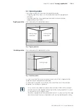
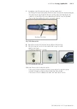
4�
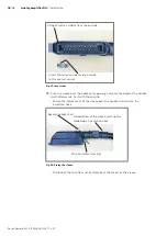
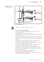
Slide the locking pieces onto both sides of the contact carrier.
Fig� 17: Locking pieces
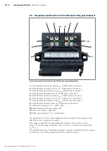
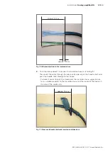
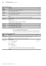
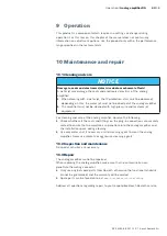
5�
Push the handle shell to the insulation hose end.
– Hang the latch of the contact carrier on the side of contacts 1 and 14 in the
internal latch of the handle shell on the side of the cable entry opening.
– The insulation hose end must reach into the handle shell by approx. 1 to
1.5 cm via the terminal area of the cable clamp.
– The contact carrier must still hang out on the opposite side of the cable entry
opening (no tension on the wires)
approx. 1 - 1.5 cm
Contact carrier hanging out
Clamping collar
Latches
Fig� 18: Bringing contact carrier into position
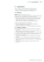
6�
Screw on the clamping collar with the corresponding screws.
– Tightening torque 0.9 – 1.1 Nm
– If the clamping of the insulation hose (e.g. with few wires) is too low,
adhesive tape has to be applied in the terminal area.


