


RE 95230-B/2021-12-01, Bosch Rexroth AG
Installation |
Analog amplifier RA 25
/48
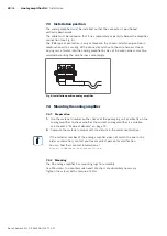
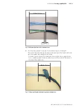
max. 12 cm
Fig� 13: Lead the wires away in a light bend
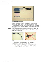
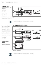
– Ensure correct stripping length (4 mm) and correct crimping
(see TE Connectivity documents 114-18022 and 114-18050).
Wire protruding max. 1 mm
Insulation crimped
Insulation not crimped
Correct crimping
Incorrect crimping
Hook
Fig� 14: Correct stripping length
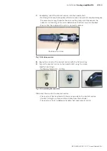
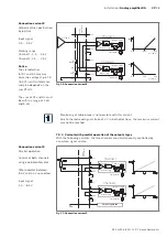
– The catch of the contact must be engaged in the detent locking of the contact
carrier.
Verify this by pulling on the line (tensile test).
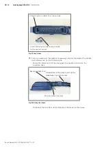
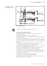
– Immediately consider internal bridges and - if necessary - wiring elements
(resistance) in the connector and install them according to the following
instructions.


