


Battery Charger
System Overview | en
9
Bosch Security Systems B.V.
Installation and Operation manual
180110011Aa | V1.1 | 2011.05
3.4
Product view
3.4.1
Indicators on the front panel
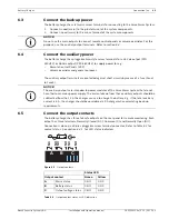
Figure 3.1
Front view of battery charger
Fault signalling occurs with three LEDs at the front side as well as three fail-safe outputs on
the rear panel for remote monitoring (refer to section
3.4.2
).
Status LED
Green
Yellow
A
Mains status
OK
- Mains voltage threshold <165 Vac ±5% (Auto
reconnect at >185 Vac ±5%).
- Primary fuse (F1) is blown.
- Power supply is broken.
- Internal battery charger temperature is too high
(>65°C).
B
Battery status
OK
- The battery is not present.
- The internal impedance (Ri) is too high
(see section
5.1
and
8.1.1
).
- When the mains is present and the battery voltage
during normal use is:
PLN-24CH12: <23.5 Vdc ±3%
PRS-48CH12: <47,0 Vdc ±3%
- When the mains is present and the battery voltage
during start-up is:
PLN-24CH12: Vbat ≤ 14 Vdc, Vbat ≥ 30 Vdc (±3%)
PRS-48CH12: Vbat ≤ 40 Vdc, Vbat ≥ 60 Vdc (±3%)
- When battery is connected in reverse when
commisioning the system
C
Output voltage status
OK
- No voltage on one or more output.
- Fuse (F8) broken.
A
B
C
xxV Battery Charger
Содержание PLN-24CH12
Страница 1: ...Battery Charger PLN 24CH12 and PRS 48CH12 en Installation and Operation manual ...
Страница 2: ......
Страница 34: ......


