


Notice!
When a master-slave configuration is used for rooms which are always separated, the delay
switch positions can be determined per system and the delay caused by transmission from
master to slave transmitter can be ignored.
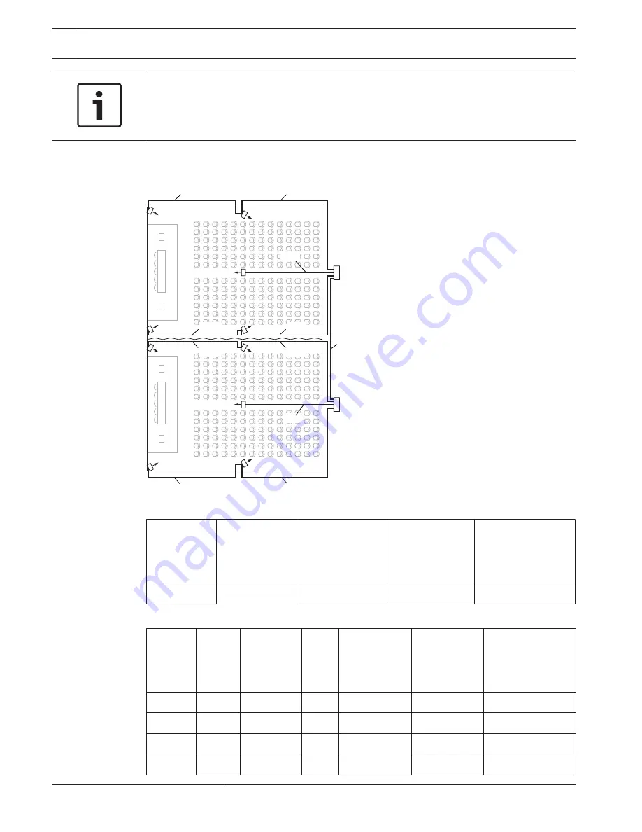
The next figure and tables and table 7.1 illustrate the calculation of the extra master-slave
signal delay.
R2
R1
R4
R6
R9
20m
R7
R5
R10
Tx2
R8
R3
Tx1
20m
30m
20m
50m
30m
20m
20m
30m
30m
20m
Figure 7.6: System with master and slave transmitter in multi purpose room
Cable length
master-slave
transmitter
[m]
Cable signal
delay per meter
[ns/m]
Cable signal
delay [ns]
Signal delay
slave transmitter
[ns]
Master-to-slave
signal delay [ns]
50
5.6
50x5.6=280
33
280+33=313
Table 7.3: Calculation of the master-to-slave signal delays
Radiator
number
Trans-
mitter
Master-to-
slave signal
delay [ns]
Cable
signal
delay
[ns]
Total signal
delay [ns]
Signal delay
difference
[ns]
Delay switch
position
1
Master
0
168
0+168=168
593-168=425
425/33=12.88=13
2
Master
0
280
0+280=280
593-280=313
313/33=9.48=9
3
Master
0
112
0+112=112
593-112=481
481/33=14.58=15
4
Master
0
168
0+168=168
593-168=425
425/33=12.88=13
64
en | Configuration
Language Distribution System
2013.11 | V1.4 |
Operation manual
Bosch Security Systems B.V.
Содержание INT-TX04
Страница 1: ...Language Distribution System Integrus en Operation manual ...
Страница 2: ......
Страница 93: ......