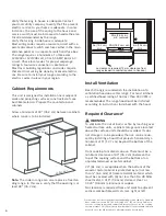
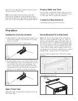
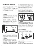
background image

11

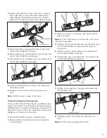
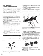
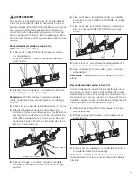
4.  Place one terminal lug (packaged with this 

manual) on each post. Replace the star washer 
and round washer and secure with 20" (50.8 cm) 
pounds of torque.

5.  Strip 3/8" (9.5 mm) of insulation from the end of 

each wire.

3/8 “

6.  Insert stripped end of white wire into the center 

lug on top of the ground strap. Secure the clam-
ping screw.

lug

clamping screw

wire

7.  Insert stripped end of red wire into the left lug. 

Secure clamping screw.

8.  Insert stripped end of black wire into the right lug. 

Secure clamping screw.

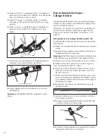
9.  Tighten each clamping screw with the appropriate 

torque (See table below).

gauge

torque (in./lbs.)

torque (Nm)

6

35

3.95

8

25

2.82

10.  Properly secure flexible conduit at knockout pa-

nel on range and at supply side junction box. The 
wiring is now complete.

green ground screw

note: DO NOT plug in range at this time.

complete the installation

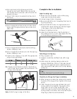
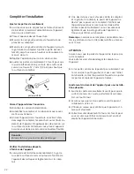
adjust leveling legs
1.  
Make sure circuit breaker is off and then plug 

range cord into electrical outlet.

2. Line up range in front of opening.
3.  Measure back left corner of opening from floor to 

top of countertop.

4.  Measure back left corner of range to bottom of 

cooktop trim. Adjust leveling leg until this height 
is the same as the corner dimension.

5. Repeat in right back corner.
6.  Adjust front leveling legs so that the bottom of 

the cooktop trim is ½" (12.7 mm) higher than the 
corresponding countertop surface.

adjustable leg

wrench

drawer

slide range into opening
1.
 Plug in power cord.
2.  Dampen countertop and foam tape with soapy 

water. 

3.  Slide range into opening, being careful not to 

damage countertops, floors, or the range drawer 
front. Do not apply pressure to cooktop when sli-
ding into position. Be careful not to crimp flexible 
connector.

tips:
Remove the drawer to prevent damage.

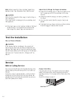
check Back of range for proper Installation
1.
  When properly installed, the cooktop trim around 

the back of the range will rest lightly on the coun-
tertop.

2.  There should not be any gap between the coun-

tertop and the trim; however, the weight of the 
range must not rest on the countertop. Look 
under the range to verify that both back legs are 
resting solidly on the floor. Also verify that the left 
range leg is under the anti-tip bracket.

Содержание HEI7052C

Страница 1: ...tructions Slide in Electric Ranges with European Convection Notice d installation Surface de cuisson électrique à convection européenne INSTRUCCIONES DE INSTALACIÓN Estufas eléctricas deslizantes con convección europea ...

Страница 2: ... 17 Application du ruban en mousse 17 Installation de la garniture du mur arrière optionnelle 17 Raccordement électrique Cordon de four 18 Raccordement électrique Câblage flexible 20 Compléter l installation 22 Vérification de l installation 23 Réparation 23 Índice Instrucciones de seguridad importantes 24 Preparación 27 Procedimiento 30 Instalación del soporte anticaídas 30 Aplicar cinta de espum...

Страница 3: ...ollow the gas sup plier s instructions If you cannot reach your gas supplier call the fire department Installation and service must be per formed by a qualified installer authorized service agency or the gas supplier WARNING Tip over hazard A child or adult can tip the range over and be killed Verify that the anti tip bracket is securely installed Ensure the anti tip bracket is engaged when the ra...

Страница 4: ...a installation must be in accordance with the CAN 1 B149 1 and 2 Installation Codes for Gas Burning Appliances and or local codes Important Local codes vary Installation electrical connections and grounding must comply with all applicable codes For appliances equipped with a cord and plug do not cut or remove the ground prong It must be plugged into a matching grounding type receptacle to avoid el...

Страница 5: ...e cooktop and may adversely affect cooking and baking performance Tips Tape warming drawer shut to keep it from ope ning while installing the range During installation place a portion of the box or a piece of cloth under the range to protect floors To make range lighter and easier to handle remove door see instructions in Use and Care manual Electrical Requirements Refer to data plate for more inf...

Страница 6: ...uired 12 mm clearance from range sidewall to cabinet required in Canada Install Ventilation Bosch strongly recommends the installation of a ventilation hood above this range For most kitchens a certified hood rating of not less than 300 CFM is recommended The range hood must be installed according to instructions furnished with the hood Required Clearance1 WARNING To eliminate the risk of burns or...

Страница 7: ... screws to the floor or to the wall Depending on floor or wall material use wood or anchorless concrete screws included Con crete screws require a 3 16 masonry bit Screws should provide firm attachment into solid wood or flooring Do not attempt to anchor into drywall Apply Foam Tape Apply foam tape to underside of cooktop trim in one continuous piece Install Backwall Trim Optional Note This step i...

Страница 8: ...k of Electric Shock or Fire Frame grounded to neutral through a ground strap Grounding through the neutral conductor is prohibited for new branch circuit installations 1996 NEC mobile homes and recreational vehicles or in an area where local codes prohibit grounding through the neutral conductor For installations where grounding through the neu tral conductor is prohibited a disconnect the link fr...

Страница 9: ...is preferred but where local codes and ordinances permit grounding through neutral and where conversion to four wire is impractical the unit may be connected to the power supply via a three wire connection 1 Disconnect electrical power at breaker box 2 Remove the terminal block cover to expose the terminal block 3 Remove top nut star washer and round washer from each post Note DO NOT remove last r...

Страница 10: ...re 3 8 9 Insert the insulated grounding wire into the lug below the terminal block 10 Insert stripped end of white wire into the center lug Secure the clampingscrew lug clamping screw wire 11 Insert stripped end of red wire into the left lug Secure clamping screw 12 Insert black wire into the right lug Secure clamp ing screw 13 Tighten each clamping screw with the appropri ate torque see table Gau...

Страница 11: ...g 3 Measure back left corner of opening from floor to top of countertop 4 Measure back left corner of range to bottom of cooktop trim Adjust leveling leg until this height is the same as the corner dimension 5 Repeat in right back corner 6 Adjust front leveling legs so that the bottom of the cooktop trim is 12 7 mm higher than the corresponding countertop surface adjustable leg wrench drawer Slide...

Страница 12: ...to ensure that anti tip bracket engages and prevents tip over Test the Installation Turn on Power at Breaker CAUTION If the display flashes and beeps the polarity of the wiring may be reversed Reversed polarity can damage the range and can result in electrical shock hazard Immediately switch off power at the breaker and return to Connect Electric Range Cord on page 8 Service See Use and Care Manua...

Страница 13: ... instructions du fournisseur de gaz Si vous ne parvenez pas à joindre votre fournisseur de gaz appelez le service d incendie L installation et les réparations doivent être effectuées par un installateur quali fié un organisme de service autorisé ou le fournisseur de gaz AVERTISSEMENT Risque de basculement Un enfant ou un adul te peut faire basculer le four et être tué Vérifiez que l étrier anti ba...

Страница 14: ...tricité locaux Au Canada l installation doit être conforme aux codes d ins tallation CAN 1 B149 1 et 2 pour les appareils à gaz et ou aux codes locaux Important Les codes locaux peuvent différer L installa tion les raccordements électriques et la mise à la terre doivent être conformes à tous les codes applicables Pour les appareils dotés d un cordon d alimentation avec fiche ne pas couper ou enlev...

Страница 15: ...pact négatif sur la cuisson Conseils Maintenez le tiroir réchaud fermé avec du ruban adhésif pour éviter qu il s ouvre au cours de l ins tallation de l appareil Au cours de l installation placez une partie de la boîte ou un linge sous l appareil pour protéger le plancher Pour que l appareil soit plus léger et facile à manipuler enlevez la porte voir les instructions dans le manuel d utilisation et...

Страница 16: ... clearance from range sidewall to cabinet required in Canada Installation de la ventilation Bosch recommande fortement d installer une hotte au dessus de cet appareil Pour la plupart des cuisines une hotte certifiée offrant au moins 91 m3 min 300 CFM est recommandée La hotte doit être installée conformément aux instructions qui l accompagnent Espacement requis1 AVERTISSEMENT Pour éliminer le risqu...

Страница 17: ... utilisez des vis en bois ou des vis à béton sans ancre comprises Les vis à béton nécessitent une mèche à maçonnerie de 4 8 mm 3 16 po Les vis devraient offrir une fixation solide dans le bois ou un plancher ferme Ne tentez pas de fixer l étrier dans une cloison sèche Application du ruban en mousse Appliquez du ruban en mousse en une seule longue bande sur la face antérieure du rebord de la surfac...

Страница 18: ... panneau amovible sous le bloc de bornes peut être retiré de l appareil au cours de l installation du serre câble Retirez le panneau de l appareil installez le serre câble et replacez ensuite le panneau NE RETIREZ PAS tout le panneau arrière de l appareil AVERTISSEMENT Risque de chocs électriques ou d incendie Le cadre est mis à la terre au neutre par une bande de mise à la terre La mise à la terr...

Страница 19: ... Resserrez la vis bande de mise à la terre vis verte de mise à la terre fil de mise à la terre 5 Fixez le fil rouge la rondelle ronde la rondelle en étoile et l écrou DANS CET ORDRE sur la tige gauche 6 Fixez le fil blanc la rondelle ronde la rondelle en étoile et l écrou DANS CET ORDRE sur la tige centrale 7 Fixez le fil noir la rondelle ronde la rondelle en étoile et l écrou DANS CET ORDRE sur l...

Страница 20: ...rre 7 Placez une attache de borne comprise avec ce ma nuel sur chaque tige Replacez la rondelle en étoile et la rondelle ronde et fixez en place avec 23 kg cm 20 lb po de couple 8 Enlevez 9 5 mm 3 8 po de revêtement isolant de l extrémité du fil 9 5 mm 3 8 po 9 Insérez le fil de mise à la terre isolé dans l attache sous le bloc de bornes 10 Insérez le bout dénudé du fil blanc dans l attache centra...

Страница 21: ...rnes pour exposer le bloc 3 Enlevez l écrou supérieur la rondelle en étoile et la rondelle ronde de chaque tige Remarque NE PAS enlever la dernière rondelle ronde le dernier écrou ou les éléments du câblage interne 4 Placez une attache de borne comprise avec ce ma nuel sur chaque tige Replacez la rondelle en étoile et la rondelle ronde et fixez en place avec 23 kg cm 20 lb po de couple 5 Enlevez 9...

Страница 22: ...l appareil 1 Lorsqu elle est installée convenablement la garni ture de la surface de cuisson autour de l arrière de l appareil devrait reposer légèrement sur le comp toir 2 Il ne devrait pas y avoir d espace entre le comptoir et la garniture toutefois le poids de l appareil ne devrait pas reposer sur le comptoir Vérifiez sous l appareil pour vous assurer que les deux pattes arrière reposent solide...

Страница 23: ...e reporter au Manuel d utilisation et d entretien Consulter la garantie dans le Manuel d utilisation et d entretien Pour contacter un technicien de dépannage voir les coordonnées sur la couverture avant du manuel Lorsque vous téléphonez soyez prêt à fournir les informations imprimées sur la plaque signalétique de votre produit Plaque signalétique du produit La plaque signalétique comporte le numér...

Страница 24: ...Siga las instrucciones del proveedor de gas Si no puede comunicarse con su provee dor de gas llame al departamento de bomberos La instalación y el servicio técnico deben ser realizados por un instalador calificado una agencia de servicio técnico autorizada o el proveedor de gas ADVERTENCIA Peligro de caída Un niño o un adulto pueden volcar la es tufa y morir Verifique que el soporte anti caídas es...

Страница 25: ...el Códi go Nacional Eléctrico establecido por la Asociación Nacional de Protección contra Incendios y aprobado por el Instituto Nacional de Normalización Estado unidense ANSI NFPA 70 última edición y con los requisitos de los códigos eléctricos locales En Ca nadá la instalación debe realizarse de conformidad con la norma CAN 1 B149 1 y 2 y los Códigos de Instalación para Electrodomésticos de Combu...

Страница 26: ... tomar el electrodo méstico por la parte trasera o desde abajo No utilice el horno ni el cajón calentador si vienen incorporados para almacenamiento Instrucciones de seguridad importantes LEA Y CONSERVE ESTAS INSTRUCCIONES Se ha realizado una prueba de este electrodomésti co de conformidad con las siguientes normas CAN CSA C22 2 No 61 Household Cooking Ranges UL 858 Household Electric Ranges ...

Страница 27: ...n puede poner en peligro el sello que rodea la placa y puede afectar el rendimiento de la cocción y del horneado en forma adversa Consejos Mantenga el cajón calentador cerrado con cinta adhesiva a fin de evitar que se abra mientras se instala la estufa Durante la instalación coloque una parte de la caja o un paño debajo de la estufa para proteger los pisos Para hacer que la estufa sea más liviana ...

Страница 28: ...lg 190 5 mm 3 1 2 pulg 88 9 mm 4 1 2 pulg 114 3 mm 4 1 2 pulg 114 3 mm 21 pulg 533 4 mm 30 pulg 762 mm Verifique que el cableado del hogar sea adecuado Comuníquese con su compañía de servicios públicos local para verificar que el servicio eléctrico actual de su hogar sea adecuado En algunos casos debe aumentarse el tamaño del cableado del hogar y del interruptor de servicio a fin de soportar la ca...

Страница 29: ... debe estar cubierto con b una plancha metálica al menos n 28 MSG de acero inoxidable de 0 015 pulg 0 4 mm o de aluminio o de cobre de 0 024 pulg 0 6 mm No se requiere ningún espacio libre desde las pa redes de la unidad hasta las paredes combustibles verticales adyacentes que se encuentran en la parte trasera en el lado derecho o izquierdo El espacio libre desde la parte superior de la estufa has...

Страница 30: ...alguno durante un máximo de un año después del día de la compra de su estufa deslizante Al hacer el pedido solicite al servicio técnico la pieza del conjunto de moldura de pared trasera N 652010 Para obtener más información consulte Requisitos de gabinetes que se encuentra en la página 28 Instale 2 tornillos a través de los orificios de la moldura y en la pared trasera de la estufa Parte trasera d...

Страница 31: ... circuito derivado como lo haría usualmente cuando el electrodoméstico se conecte a través de un conjunto de cables utilice un cable de 4 conductores para este fin Utilice solo los conjuntos para cables con capacidad nominal de 125 250 voltios como mínimo 30 A y que tengan la etiqueta Para uso con estufas El aliviador de tensiones que se proporciona con el cable debe instalarse según las instrucci...

Страница 32: ...mbres no sea posible la unidad puede conectarse a la alimentación eléctrica a través de una conexión de tres alambres 1 Desconecte la alimentación eléctrica en la caja de disyuntores 2 Retire la cubierta del bloque de terminales para dejar expuesto el bloque de terminales 3 Retire la tuerca superior la arandela dentada y la arandela redonda de cada borne Nota NO retire la última arandela redonda l...

Страница 33: ...a debajo del bloque de terminales 7 Coloque una lengüeta de terminales suministrada con este manual en cada borne Vuelva a colo car la arandela dentada y la arandela redonda y fije con un par de torsión de 20 pulg libras 50 8 cm 8 Corte 3 8 pulg 9 5 mm de aislamiento del extre mo del alambre 3 8 pulg 9 Introduzca el alambre de conexión a tierra aislado en la lengüeta que se encuentra debajo del bl...

Страница 34: ...da y la arandela redonda y fije con un par de torsión de 20 pulg libras 50 8 cm 5 Corte 3 8 pulg 9 5 mm de aislamiento del extre mo de cada alambre 3 8 pulg 6 Introduzca el extremo pelado del alambre blanco en la lengüeta central que se encuentra en la par te superior de la correa de conexión a tierra Fije el tornillo de sujeción lengüeta alambre tornillo de sujeción 7 Introduzca el extremo pelado...

Страница 35: ... adecuada 1 Si se instala de manera adecuada la moldura de la placa que rodea la parte trasera de la estufa se apoyará levemente sobre la encimera 2 No debe haber ninguna separación entre la encimera y la moldura sin embargo el peso de la estufa no debe apoyarse sobre la encimera Observe debajo de la estufa para verificar que ambas patas traseras estén firmemente apoya das sobre el piso También ve...

Страница 36: ...tufa y puede ocasionar peligro de descar gas eléctricas Apague la alimentación eléctrica en el disyuntor inmediatamente y regrese a Conectar el cable eléctrico de la estufa que se encuentra en la página 30 Servicio técnico Para obtener información sobre resolución de prob lemas consulte el Manual de uso y cuidado Consul te la garantía en el Manual de uso y cuidado Para consultar a un representante...

Страница 37: ...Notes ...

Страница 38: ...Notes ...

Страница 39: ......

Страница 40: ...1901 Main Street Suite 600 Irvine CA 92614 800 944 2904 www boschappliances com 9000695896 5V0NHA Rev B 07 12 BSH Home Appliances Corporation ...

Отзывы: