© 2004 Bosch Security Systems
130 Perinton Parkway, Fairport, New York, USA 14450-9199
Customer Service: (800) 289-0096; Technical Support: (888) 886-6189
03/04
DX2010 Installation Instructions
P/N: 49533E Page 4
4.5 Tamper Point/Zone Inputs
This feature is not available for some control/communicators.
Consult your control/communicator’s Installation Instructions.
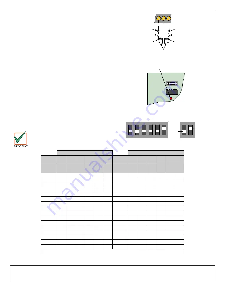
The DX2010 has the capacity for dual tamper point/zone inputs
utilizing two EOL resistors (using 1.5k or 2.2k Alarm Resistor). See
Figure 11.
5.0
DX2010 LED Operation
The DX2010 LED (Figure 12) flashes to indicate the status of the
device. The LED indications are:
• One flash per second indicates normal operation.
• LED steady ON can indicate any of the following:
- G wire is not connected or there is a communications problem
between the control panel and the DX2010.
- No locations/points are assigned to the DX2010 with this
address. See your control/communicator’s programming
guide for location/point assignment instructions.
- Address on the DX2010 is not set correctly.
• LED OFF indicates that there is no power to the module.
6.0
Setting the DX2010’s Address
Use Table 2 to configure the DX2010’s address. Refer to the control/
communicator’s installation manual to determine the appropriate
address for each DX2010 you connect. Figure 13 shows the DIP
switch configuration.
Each time you change the address DIP switches,
cycle the power to the DX2010 (turn the power off
and then on) for the address change to take effect.
L+
COM
L+
2.2 k
EOL
Resistor
2.2 k
EOL
Resistor
1.5 k or 2.2 k
Alarm
Resistor
1.5 k or 2.2 k
Alarm
Resistor
Alarm
Contacts
Tamper
Contacts
Tamper
Contacts
Figure 11: Dual Point/Zone Input Wiring
ON
1
2
3
4
5
6
Status LED
Figure 12: DX2010 Status LED
ON
1
2
3
4
5
6
OFF
ON
Example:
Module Address 102
Figure 13: DIP Switch Configuration
DIP Switch Settings
DIP Switch Settings
DIP
Switches
S1
S2
S3
S4
S5
S6
DIP
Switches
S1
S2
S3
S4
S5
S6
Module
Address
32
16
8
4
2
1
Module
Address
32
16
8
4
2
1
101
OFF OFF OFF OFF OFF OFF
117
OFF ON
OFF OFF OFF OFF
102 OFF
OFF
OFF
OFF
OFF
ON
118 OFF
ON
OFF OFF OFF ON
103 OFF
OFF
OFF
OFF
ON
OFF 119 OFF
ON
OFF OFF ON
OFF
104 OFF
OFF
OFF
OFF
ON ON 120 OFF
ON
OFF OFF ON ON
105 OFF
OFF
OFF
ON
OFF OFF
121
OFF ON
OFF
ON
OFF OFF
106 OFF
OFF
OFF
ON
OFF
ON
122 OFF
ON
OFF
ON
OFF
ON
107 OFF
OFF
OFF
ON ON OFF 123 OFF
ON
OFF
ON ON OFF
108 OFF
OFF
OFF
ON ON ON 124 OFF
ON
OFF
ON ON ON
109 OFF
OFF
ON
OFF OFF OFF
125
OFF ON ON OFF OFF OFF
110 OFF
OFF
ON
OFF OFF ON
126 OFF
ON ON OFF OFF ON
111 OFF
OFF
ON
OFF
ON
OFF 127 OFF
ON ON OFF
ON
OFF
112 OFF
OFF
ON
OFF
ON ON 128 OFF
ON ON OFF
ON ON
113 OFF
OFF
ON ON OFF OFF
129
OFF ON ON ON OFF OFF
114 OFF
OFF
ON ON OFF
ON
130 OFF
ON ON ON OFF
ON
115 OFF
OFF
ON ON ON OFF 131 OFF
ON ON ON ON OFF
116 OFF
OFF
ON ON ON ON 132 OFF
ON ON ON ON ON
ON indicates the DIP switch is in the ON position; OFF indicates the DIP switch is in the OFF position.
Table 2: Address Jumper Settings


