DICENTIS
System installation design and planning | en
25
Bosch Security Systems B.V.
Hardware Installation Manual
2021.01 | V2.2 |
Calculation examples
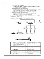
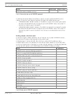
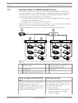
The following example gives you an indication of the maximum load to each socket of an Audio
processor and powering switch or Powering switch.
–
Socket 2
: 50 m cable + DCNM-MMD2 =
12 W
1
–
Socket 3
: 10 m cable + DCNM-MMD2 + 9x (2 m cable + DCNM-MMD2)
= (4.5 + 12) + 9x(1.19 + 12) =
135.21 W
2
.
–
Socket 4
: 10 m cable + DCNM-D + 19x (2 m cable +DCNM-D)
= (4.5 + 3.1) + 19x(1.19 + 3.1) =
89.11 W
2
.
–
Socket 5
: 10 m cable + DCNM-DE + 19x (2 m cable + DCNM-DE)
= (4.5 + 5) + 19x(1.19 + 5) =
127.11 W
2
.
1
For socket 2, the cable power consumption of the cable does not need to be counted if only one device is connected to this output.
2
The shortest redundant cable does not need to be counted.
Refer to
–
Calculation using PoE switches, page 25
4.3.2
Calculation using PoE switches
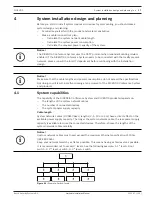
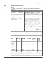
Select one or more PoE Ethernet switches to supply power to the DICENTIS devices. Each
DICENTIS device must be connected to an individual PoE enabled output of an Ethernet
switch.
i
Notice!
Some PoE Ethernet switches can only supply power to a limited number of ports. Others can
supply power to every port, but the total power the Ethernet switch can supply is limited.
Please consult the documentation of the PoE Ethernet switch used.
i
Notice!
Using PoE, DICENTIS devices cannot be daisy‑chained connected. Using PoE does not provide
redundant cabling.
Содержание DCNM-APS2
Страница 1: ...DICENTIS Conference System en Hardware Installation Manual ...
Страница 2: ......
Страница 78: ...78 Installation Test DICENTIS 2021 01 V2 2 Hardware Installation Manual Bosch Security Systems B V ...
Страница 79: ......

