D278S/D298S
|
Installation Guide || 1.0
Overview
2
Bosch Security Systems, Inc. | 11/10 | F01U069160-11
1.0 Overview
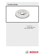
These instructions cover installing the D278S (12 V) or
D298S (24 V) Addressable Smoke Detector Bases in an
addressable system controlled by a D9412G/D7412G
or later 12 V Fire Alarm Control Panel (FACP) with a
D8125 POPEX Module and 12 V or 24 V auxiliary
power or a D9124 24 V FACP.
The D278S and D298S have a built-in POPIT to
provide individual addresses on the FACP data
expansion circuit. These bases accept:
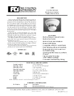
D285 Series Photoelectric Smoke Detector Heads
D286 Ionization Smoke Detector Head
D603, D604, and D605 Heat Detector Heads
When used with the D285 Series Detectors, the D278S
and D298S indicate chamber check trouble to the
control panel through the POPIT bus. The chamber
check trouble indication appears on the control stations
as a fire trouble.
If using the D278S and D298S
Addressable Smoke Detector Bases as
replacements in a system controlled by a
9000 Series or G Series or later control
panel, follow that control panel’s address
(point assignment) setting instructions and
set the base address switch (Switch 0) to
ON.
2.0 Mounting
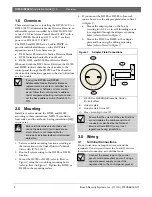
Install, test, and maintain the D278S and D298S
according to these instructions, NFPA 72 standards,
local codes, and the authority having jurisdiction (AHJ)
in your area.
Failure to follow these instructions can
cause the detector to fail to indicate an
alarm. Bosch is not responsible for
improperly installed, tested, or maintained
detectors.
1.
Select a suitable mounting location according to
the instructions in the Smoke Detectors Technical
Service Note (P/N: 31347).
2.
Route all system wiring to the D278S or D298S
location.
3.
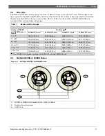
Mount the D278S or D298S (refer to Item 1 in
Figure 1) using the two oblong mounting holes
(refer to Item 4 in Figure 1). Tighten the D278S or
D289S to the mounting surface.
4.
If you mount the D278S or D298S to four-inch
square boxes, use the adapter plate (refer to Item 2
in Figure 1):
a.
Mount the adapter plate on the box by
screwing two 6-32 x 1-in. self-threading screws
(not supplied) through the adapter mounting
holes (refer to Item 3 in Figure 1).
b.
Mount the D278S or D298S to the adapter
plate and box using the oblong mounting
holes (refer to Item 4 in Figure 1).
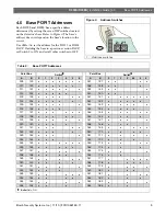
Figure 1:
Adapter Plate Connections
1
2
4
3
1 - D278S or D298S Addressable Smoke
Detector Base
2 - Adapter plate
3 - Adapter plate holes (2)
4 - Base mounting holes (2)
Ensure that the volume of the electrical box
accommodates the number and size of
conductors specified by the National
Electrical Code (NEC) or any local
regulations having jurisdiction.
3.0 Wiring
3.1 Terminal
Connections
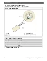
Do not twist wires or loop the wires around the
terminals. Cut, strip, and insert the In and Out wires
for terminal connection as individual ends.
Connect the power loop to the control
panel’s switched auxiliary power. If using a
separate power supply, connect the
negative side to the control panel ground.

