background image

1 4  |


Bosch ZS Series Zone Sensors R1


Installation & OperationManual

02.2018 

|

 Bosch Thermotechnology Corp.

Data subject to change

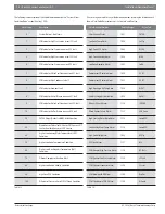
The following is a description of the available alarm codes on the “Current Alarm 
Condition/Code” screen(Rnet tag 1300):

Alarm Code

Description

0

System Normal - No Alarms

1

UPM code for High Pressure on circuit #1 fault

2

UPM code for Low Pressure on circuit #1 fault

3

UPM code for High Pressure on circuit #2 fault

4

UPM code for Low Pressure on circuit #2 fault

5

UPM code for Water Coil Freeze on circuit #1 fault

6

UPM code for High Condensate fault

7

UPM code for Brownout fault

8

UPM code for Air Coil Freeze on circuit #1 fault

9

UPM code for Water Coil Freeze on circuit #2 fault

10

UPM code for Air Coil Freeze on circuit #2 fault

20

FHP560 Input/Output in MANUAL lock position

30

Wired Sensor Failure for ZS Sensor, DAT Sensor, LWT 
Sensor, Humidity Sensor or CO2 Sensor

40

High or Low Leaving Water Temperature (LWT) 
Condition

50

High or Low Zone Temperature Condition

60

High or Low Discharge Air Temperature (DAT) 
Condition

70

Filter or Compressor Runtime Alert

80

High or Low Zone Humidity Condition

90

High Zone CO2 Condition

100

Diff erential Pressure Switch (DPS) Open Condition

Table 13


If an alarm is generated for any of the below conditions, pressing the info button will 
show a Alarm Code Description short “active text” and Rnet tag:

Alarm Display Information

Rnet Tag Number

Active Text

Filter Change Status

1027

FILTER

Low Zone Temp Alarm

1026

Lo ZTp

High Zone CO2 Alarm

1043

HI CO2

High Zone Humidity Alarm

1044

HI RH

Low Zone Humidity Alarm

1045

Lo RH

Compressor1 Runtime Alarm

1050

C1 RT

Compressor2 Runtime Alarm

1051

C2 RT

High Discharge Air Temp Alarm

1028

Hi DAT

Low Discharge Air Temp Alarm

1029

Lo DAT

Manual I/O Lock Alarm

1116

IO OVRD

Wired Sensor Failure Alarm

1115

SEN Conn

High Leaving Water Temp Alarm

1113

Load H2O

Low Leaving Water Temp Alarm

1114

Load H2O

High Zone Temp Alarm

1025

Hi ZTp

DPS Lock Alarm

1117

dPS

UPM General High Pressure Alarm

1118

HP Fault

UPM General Low Pressure Alarm

1119

LP Fault

UPM General Freezestat Alarm

1120

Frz stat

UPM Brownout BRN Alarm

1109

Brn Out

UPM Condensate COND Alarm

1108

Hi Cond

Table 14


Содержание 8733951033

Страница 1: ...Bosch ZS Series Zone Sensors R1 Compatible with DDC Control Air 5600 5830 and 6120 Controllers Installation Operation Manual ...

Страница 2: ...2 Bosch ZS Series Zone Sensors R1 Installation OperationManual 02 2018 Bosch Thermotechnology Corp Data subject to change ...

Страница 3: ...r Sensors 10 9 1 Navigating the Push Manager Sensor s Screens 10 9 2 ZS Push Sensor Display 10 9 3 ToMaketheZoneWarmerorCoolerUsingaZSPush Manager 11 9 4 To Override the Schedule Using a ZS Push Manager 11 9 5 To Lock the Sensor Buttons of a ZS Push Manager 12 9 6 To Edit Displayed Values Using a ZS Push Manager 12 9 7 Rnet Tags 12 10 Troubleshooting 15 10 1 Battery Reset 15 11 Wiring and Mounting...

Страница 4: ... avoided will result in death or serious injury WARNING indicates a hazardous situation which if not avoided could result in death or serious injury CAUTION indicates a hazardous situation which if not avoided could result in minor to moderate injury NOTICE is used to address practices not related to personal injury Important information This symbol indicates important information where there is n...

Страница 5: ...ncludes the ZS Base ZS Slidebar ZS Push and ZS Manager2 Figure 1 ZS 1 ZS 1H ZS Base ZS 1S ZS Slidebar ZSP 1 ZSP 1H ZSP 1HC ZS Push ZSM 1 ZSM 1H ZSM 1HC ZS Manager ZS Series Sensors Features Model ZS 1 ZS 1H ZS 1S ZSP 1 ZSP 1H ZSP 1HC ZSM 1 ZSM 1H ZSM 1HC Part Number 8733951033 8733951034 8733951035 8733951036 8733951037 8733951038 8733951039 8733951040 8733951041 Temperature Humidity CO2 Neutral c...

Страница 6: ...cifications SensingElement Range Accuracy Temperature On Non Humidity Models 4 F to 122 F 20 C to 50 C 0 35 F 0 2 C Temperature On Humidity Models 50 F to 104 F 10 C to 40 C 0 5 F 0 3 C Humidity 10 to 90 1 8 typical CO2 400 to 1250 PPM 1250 to 2000 PPM 30PPM or 3 of reading greater of two 5 of reading plus 30 PPM Table 3 PowerRequirements SensorType Power Required Temperature Only All Models 12Vdc...

Страница 7: ...dings for temperature is required Sensor Features ZS Base Local access port No user control Available in Temperature only ZS 1 8733951033 Temperature with Humidity ZS 1H 8733951034 Table 5 Sensor Features ZS Slidebar Slide potentiometer for temperature setpoint adjustment to make the zone warmer or cooler button to override the schedule and put the zone in an occupied state Green LED to indicate o...

Страница 8: ...erature with Humidity ZSP 1H 8733951037 Temperature with Humidity and CO2 ZSP 1HC 8733951038 Table 7 Sensor Features ZS Manager LCD Display button to override the schedule and put the zone in an occupied state or force the zone to an unoccupied state and buttons to change any editable property such as the temperature or humidity set point button to cycle through information defined in the control ...

Страница 9: ... is 9 Figure 3 DIP Switch value 1 ON 2 4 8 1 2 3 4 While the DIP switches may be used to address the sensor for any value from 0 to 14 the DDC Control Air 5600 5830 and 6120 controllers ONLY recognize values from 1 to 5 and any other address will result in the sensor s not functioning properly To be released in 2018 7 Multiple Sensors Multiple ZS Series Zone Sensors on an Rnet must be configured in...

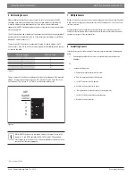
Страница 10: ...tion is in each screen and what you can adjust The type of sensor also determines what you see For example if the sensor reads temperature humidity and CO2 the Home screen will cycle through the current values ThisScreen DisplaysWhen Home The sensor has had no user interaction for 5 seconds Set point adjustment You press the or button Information You press the button Tap the button to cycle throug...

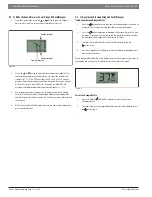
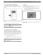
Страница 11: ...s at 0 until the next manual adjustments in the space 4 Wait a few seconds until the display returns to the home screen before you press any other buttons 9 4 To Override the Schedule Using a ZS Push Manager Timed Override to an Occupied State 1 Press the button one time to override the schedule and put the zone in an occupied state for a length of time specified in the control program 2 Press the ...

Страница 12: ...itable from the sensor An example is the screen for the zone humidity setpoint Access this screen by pressing the info button several times approx 7 times until the humidity setpoint is visible Rnet tag 406 then follow the steps below to change the value as needed max of 95 rh min of 20 rh 1 Press the or button to adjust the value 2 Wait until the display returns to the home screen before you pres...

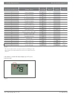
Страница 13: ...oor Air Temperature OAT 300 9 Aux Heat Output Command 1102 Off On 10 Effective Discharge Air Temperature DAT 304 11 Leaving Water Temperature LWT 319 12 Current Alarm Condition Code 1300 13 Zone Mode Status 501 14 Compressor Stage 1 Status 1100 C1 Off C1 On 15 Compressor Stage 2 Status 1101 C2 Off C2 On 16 Economizer Mode Status 116 Econ Off Econ On Table 12 If there s an active alarm s condition pre...

Страница 14: ...on 60 High or Low Discharge Air Temperature DAT Condition 70 Filter or Compressor Runtime Alert 80 High or Low Zone Humidity Condition 90 High Zone CO2 Condition 100 Differential Pressure Switch DPS Open Condition Table 13 If an alarm is generated for any of the below conditions pressing the info button will show a Alarm Code Description short active text and Rnet tag AlarmDisplayInformation RnetTa...

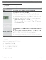
Страница 15: ... interface to verify that software version for the DDC controller is dated 06 2015 or later The DDC Control Air 6120 FLEX will have ZS support capability by end of 2018 Characters that seem out of place or jumbled The sensor has a memory problem Try formatting the sensor per the instructions provided in this document see Section 8 Formatting Sensors Bogus values 999 displayed for RH and or CO2 The...

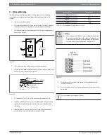
Страница 16: ... insulation Outer jacket Foil shield 25 in 6 cm Shield wire 6 6 Strip about 25 inch 6 cm of the inner insulation from each wire 7 If wiring 1 cable to the ZS Sensor cut the shield wire off at the outer jacket then wrap the cable with tape at the outer jacket to cover the end of the shield wire 8 Insert the other 4 wires into the ZS Sensor s screw terminal connector If wiring 2 cables insert like co...

Страница 17: ...ne Sensors R1 17 Bosch Thermotechnology Corp 02 2018 Data subject to change 12 ZS Series Zone Sensor R1 Dimensions Figure 12 2 75 same for all 4 75 same for all 0 80 13 Compatible Controllers Figure 13 ControlAir 5600 ControlAir 6120 ControlAir 5830 ...

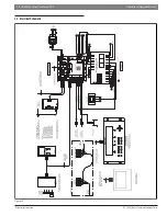
Страница 18: ...nse 12V Rnet Rnet Gnd Gnd Rnet Rnet 12V IN 1 Gnd IN 2 Gnd IN 3 Gnd IN 4 Gnd Gnd IN 5 IN 6 LED DO 3 DO 2 DO 1 BUS DO 4 DO 5 Gnd Hot Power Run Error IN 1 IN 2 DO5 DO4 DO3 DO2 DO1 POWER RUN ERROR RXD TXD Off Off On On Off Off Off On Option Card On On UNIT PROTECTION MODULE UPM SETTINGS LOCKOUT 4 2 RESET R Y ALARM CONT PULSE TEST YES NO COM UDD OUT FZ2 FZ1 MODELS ZS 1 p n 8733951033 ZS 1H p n 87339510...

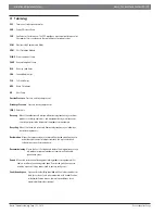
Страница 19: ...ners and equipment during maintenance or servicing or prior to the disposal of the products or equipment Recycling Means the reuse of a recovered fluorinated greenhouse gas following a basic cleaning process Reclamation Means the reprocessing of a recovered fluorinated greenhouse gas in order to match the equivalent performance of a virgin substance taking into account its intended use Decommissioni...

Страница 20: ...Fan EVAP Evaporator EW Entering Water F Fahrenheit FM Flow Meter FSS Fan Status Switch HGRH Hot Gas Re Heat HP Heat Pump HW Hot Water IEM Input Expansion Module LP Loop Pump Table 17 Abbreviation Description LW Leaving Water MA Mixed Air MAX Maximum MIN Minimum MINS Minutes MISC Miscellaneous MOD Modulating NC Normally Closed NO Normally Open OA Outdoor Air OAD Outdoor Air Damper OCC Occupancy R H...

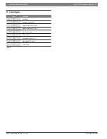
Страница 21: ...gy Corp 02 2018 Data subject to change 17 Control Signals Signal Description G Fan Signal O Reversing Valve Signal Y1 Compressor Stage 1 Signal Y2 Compressor Stage 2 Signal W Electric Heat Signal H Reheat Signal EV Economizer Valve Signal CV Condenser Valve Signal P Pump Signal Table 19 ...

Страница 22: ...22 Bosch ZS Series Zone Sensors R1 Installation OperationManual 02 2018 Bosch Thermotechnology Corp Data subject to change NOTES ...

Страница 23: ...Installation Operation Manual Bosch ZS Series Zone Sensors R1 23 Bosch Thermotechnology Corp 02 2018 Data subject to change NOTES ...

Страница 24: ...United States and Canada Bosch Thermotechnology Corp 65 Grove Street Watertown MA 02472 Tel 866 642 3198 Fax 954 776 5529 www boschheatingandcooling com BTC 469403101 A 02 2018 ...

Отзывы: