


Appendix 61/64
3 842 358 792/2016-12, Material and information fl ow technology: HQ 2/C-H, HQ 4,
Bosch Rexroth AG
17.1.2
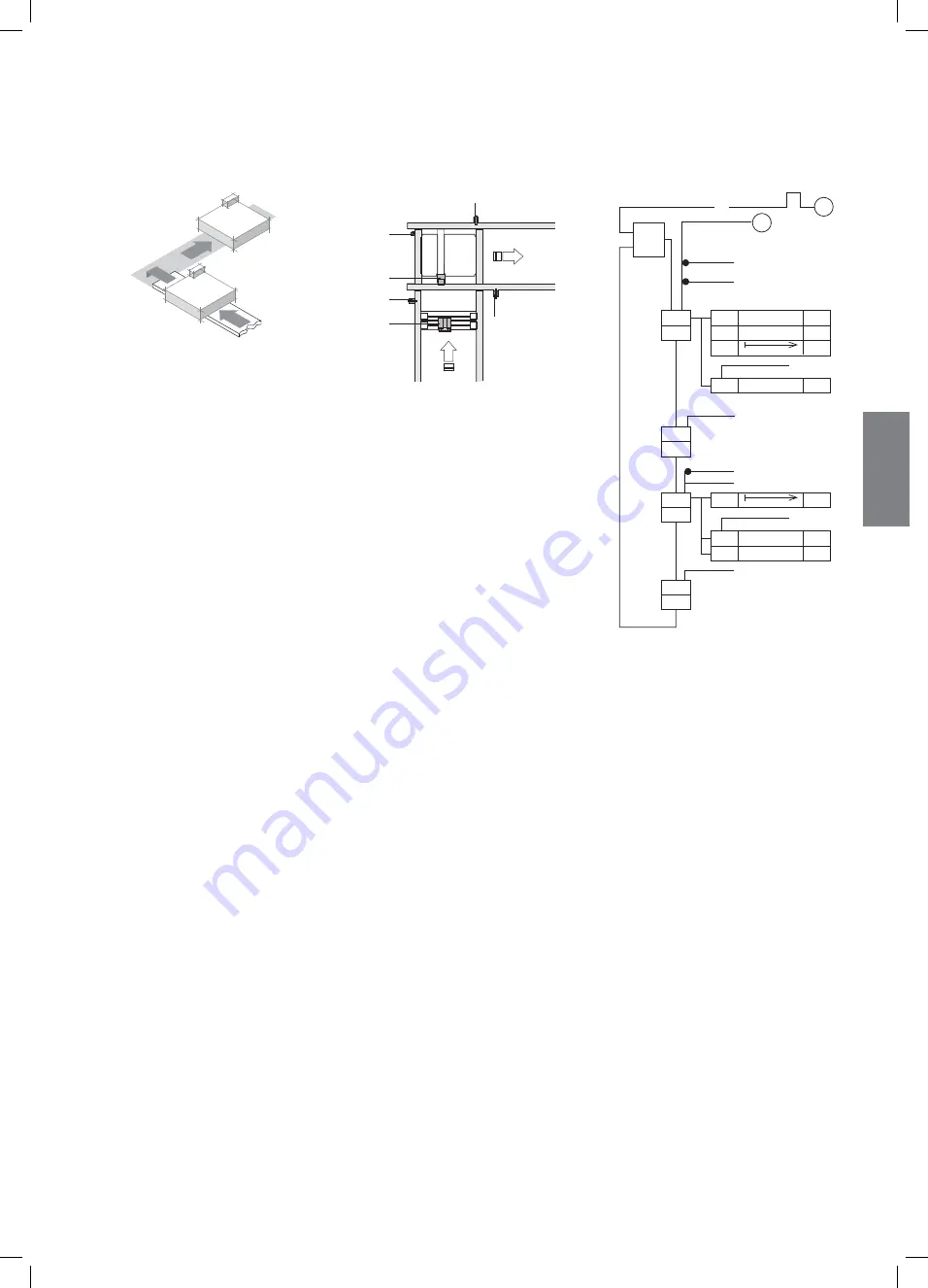
Transfer to longitudinal section (TFE 2)
Schema3
S3
Z1
S1
Z4
Z2
S2
S2
S3
S1
S1
S2
S3
1N1
1N2
1N3
1N4
NS
Y1
NS
F
T
T
F
T2
D
NS
T2
D
(Z1)
NS
Y3
(Z2)
S
Y2
(Z2)
R
Y2
(Z2)
NS
Y4
(Z4)
2
1
≥1
Start pulse after end of start-up
Release cyclic travel
S1
=
WT after VE
S2
=
WT in position on HQ
S3
=
Release adjacent section, HQ free
Y1
=
Adjacent section VE (Z1)
Y2
=
HQ up (Z2)
Y3
=
HQ down (Z2)
Y4
=
Extend DA damper (Z4)
Note:
• Distance Z1–Z3 = b
WT
+ 200 mm
EN
GLISH
551261_2016_12_EN.indd 61
551261_2016_12_EN.indd 61
22.12.2016 10:26:36
22.12.2016 10:26:36