Assembly 19/64
3 842 358 792/2016-12, Material and information fl ow technology: HQ 2/C-H, HQ 4,
Bosch Rexroth AG
7.5
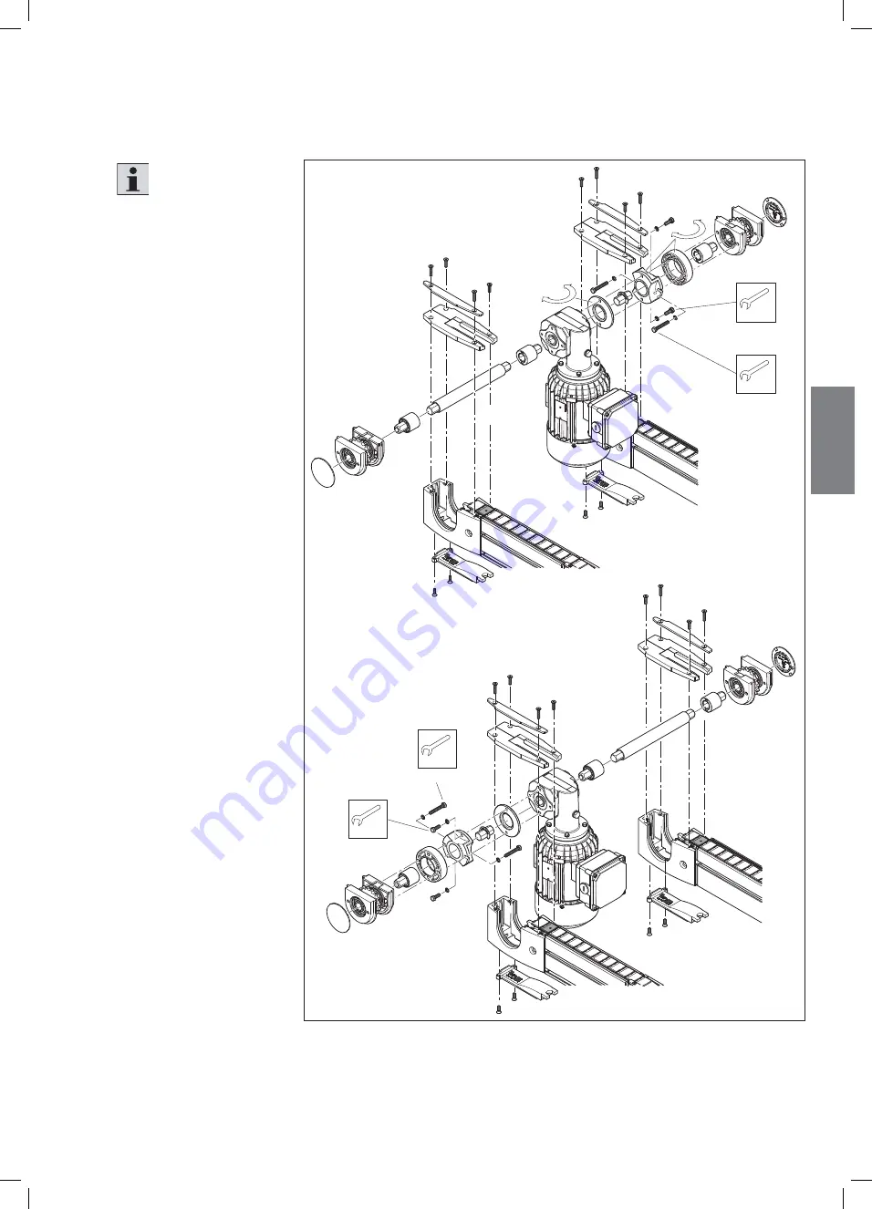
Conversion to motor mounting M left (by customer)
Fig. 6:
2x
SW13
2x
SW13
551 261-50
180°
A
B
180°
2x
M
D
=25 Nm
SW13
2x
M
D
=25 Nm
SW13
Conversion to motor mounting M left (by customer)
Please note
(
Only if necessary):
The customer has to switch
from motor mounting M
standard (on right) to motor
mounting M on left before
installing the lift transverse
unit.
A:
Motor mounting M
standard (right)
B:
Motor mounting
M left (customer
conversion)
For removal of the power
train, see Section 10.4.3
“Replacing the
transmission, internal
motor mounting” on
page 48.
Rotate the drive axis 180°
before installation (B).
The transmission will
stay aligned.
Install the power
train and belt section
in reverse order of
that described in
Section 10.4.3
“Replacing the
transmission, internal
motor mounting” on
page 48.
EN
GLISH
551261_2016_12_EN.indd 19
551261_2016_12_EN.indd 19
22.12.2016 10:26:35
22.12.2016 10:26:35


