


16992000121
2014-11-07
|
Robert Bosch GmbH
Getting Started | MTS 6513 VCI | 7
en
en
via the DLC cable when you are configuring the VCI for
wireless communication.
Some important information about powering your MTS
6513:
$
12 volts is required for vehicle diagnostics.
$
12 volts is required for wireless configuration
and use.
$
5V (USB) or 12V (Vehicle DLC) is required for
MTS 6513 firmware update or recovery.
4.10.3 SuperCap
The MTS 6513 includes a SuperCap function which
retains power for a few seconds after power has been
removed from the unit. To avoid unexpected Power OFF
events, do not change the configuration of the Super-
Cap to 'Disabled'.
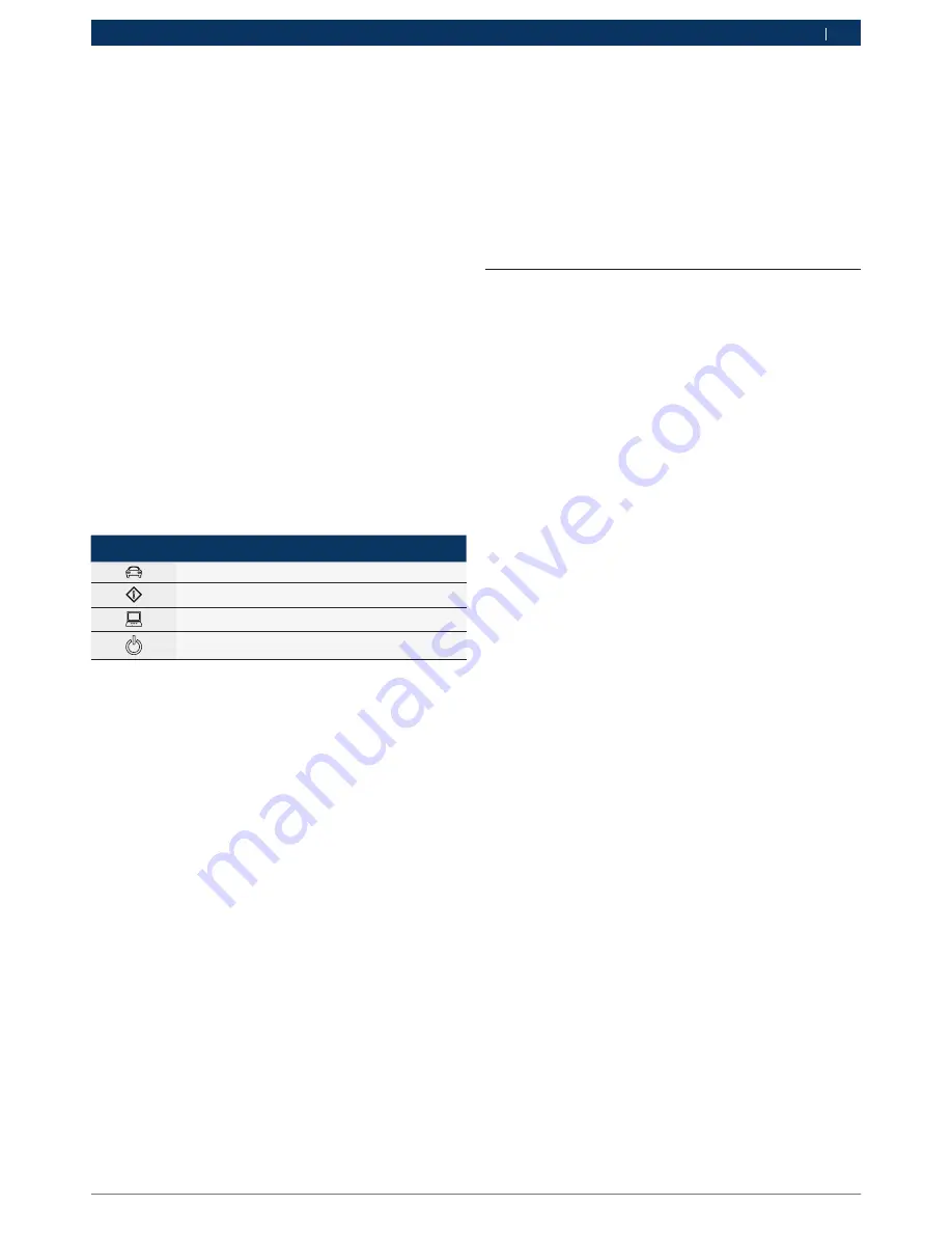
4.10.4 LCD Display
The MCI has a high-resolution monochromatic LCD
display. The LCD display provides the following status
information.
LCD Symbol Function
Vehicle Communication
Error Indicator
PC Host Communication
Power On
4.10.5 Keypad
The MTS 6513 provides an 8-key keypad including a
Home key, an Enter key, two Function keys (F1/F2), and
four Arrow keys. You can use the keypad to adjust LCD
screen settings and configure the SuperCap function.
Adjust LCD Screen Settings:
R
Depress the Home-Enter-F2 keys simultaneously to
reach the Main Menu screen.
R
Select the Screen sub-menu using the up-arrow/
down-arrow keys.
R
Use the right-arrow key to navigate to the Screen
sub-menu.
R
In the Screen sub-menu, use the up-arrow/down-
arrow keys to select either Contrast or Backlight,
use the right-arrow key to navigate to the selected
setting.
R
Use the up-arrow and down-arrow keys to adjust
Contrast and Backlight.
R
Press the left-arrow key to save your settings and go
back to the previous screen.
Configure the SuperCap Function:
R
Depress the Home-Enter-F2 keys simultaneously to
reach the Main Menu screen.
R
Select the SuperCap sub-menu using the up-arrow/
down-arrow keys.
R
Use the right-arrow key to navigate to the SuperCap-
sub-menu.
R
In the SuperCap sub-menu, use the up-arrow/down-
arrow keys to select either Enabled or Disabled.
R
Press the left-arrow key to save your settings and go
back to the previous screen.
4.11 Supported Vehicle Interfaces
The following sections list the vehicle communication
interfaces supported by the MTS 6513.
4.11.1 Serial Data Interfaces
The MTS 6513 supports the following Serial Data Inter-
faces.
VCI Physical Layer Interfaces:
R
One HS Can Channel at 125/250/500/1000 kbps
R
Two UART channels (K & L Lines)
Protocol Interfaces:
R
ISO 15765
R
ISO 14229 UDS on CAN
R
ISO 14230 KWP 2K
R
ISO 9141-2
R
ISO 11898-2
R
GMW 3110 (GM LAN)
R
SAE J1939
R
SAE J2740 (GM UART)
R
SAE J2818 - KWP 1281
R
SAE J2190
R
Honda 92HM
R
Honda 99B
4.11.2 Non-Serial Data Interfaces
The MTS 6513 supports the following Non-Serial Data
Interfaces.
R
Variable Threshold Discrete Inputs (using UART Re-
ceiver) Capable of performing timing measurements
R
Output: Open Drain using UART Driver
R
Analog Voltage measurement on Vbat and one other
pin
5. Getting Started
The following sections provide the information needed
to begin using the MTS 6513 including installing the VCI
Manager software, updating the firmware on the device,
configuring connection methods, and communicating
with the vehicle.


