620 16
th
Street #300, Denver Colorado 80202 720-961-4056
www.borgdisplays.com
BORG DISPLAYS
Introduction:
Congratulations on your purchase of a Protégé touchscreen. This manual primarily covers the hardware
features and network essentials of the Protégé screen. As you read through this manual you will learn:
1. Protégé assembly and installation
2. Hardware features
3. Connections and Wiring
4. Software options
5. FAQ Support
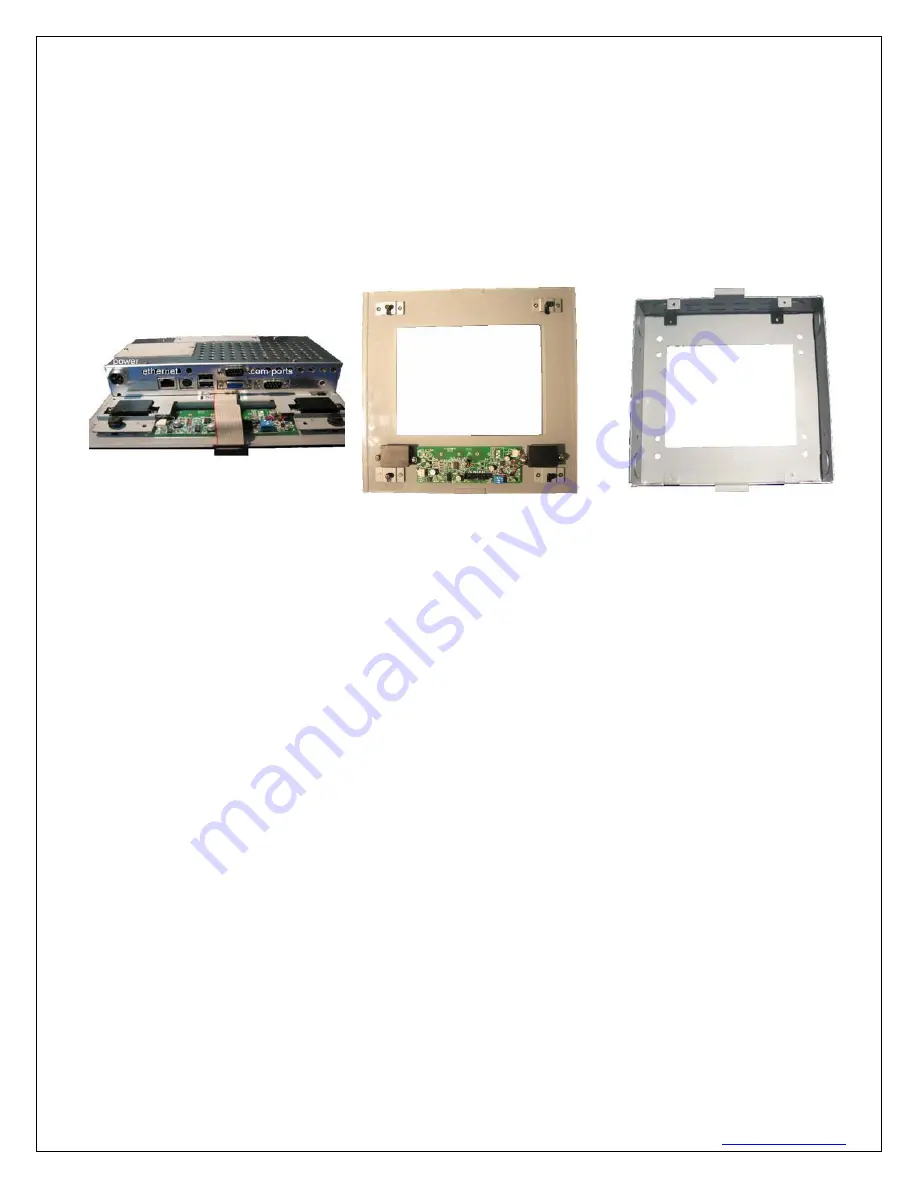
Main Unit
Bezel
Backbox
NOTE:
The installation of Protégé should be performed by professional integrators. The following discussion
offers guidance based on standard physical configurations.
Assembly:
Protégé applies to most Protégé configurations with the following primary components:
-
main unit – the electronics and display assembly
-
snap-on front cover or bezel
-
outer, rear metal housing, “Back-box” (mating screws to main unit provided)
-
power supply, documentation CD, printed manual and collateral materials
Protégé is typically shipped with the Back-box and the Bezel detached from the Display Assembly. When the
bezel is separated from the system, fragile elements such as the display, fine wiring cables, electronic circuitry
may be exposed. Always exercise caution while supplying power and against damaging the exposed device
elements when handling the Display Assembly.
The Back-box may be optional in some deployments, but may be relevant for certain installations to provide an
added barrier for environmental shielding and limiting access to input/output connections.
It is strongly
advised that the Back-box implementation be considered as the preferred approach. Borg will not
warrant INSTALLATIONS WITHOUT THE BACK-BOX.
Back box Installation:
PRE-DRYWALL - Unit should be affixed to the stud inset / flush to the stud where drywall will cover the unit.
One would then go in and cut out the bbox enclosure including over the 4 screw tabs. Then using
longer
metal screws (not included)
, insert and screw in assembly. The outer left/right tabs on the assembly will


