16
17
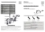
Washer
Hose
Diverter
Handset
Installation - Shower hose
Washer
Hose
Shower head
Washer
Riser arm
Shower head
Make sure there is a rubber washer in
place in the shower head and screw onto
the riser arm.
Handset
Place one of the rubber washer into the
cone end of the hose and screw to the
handset.
Valve
Place the second rubber washer into the
nut end of the hose and attach it to the
diverter outlet.
Commissioning
The valve has been factory set under
balanced pressures and hot supply at 65°C.
When your specific operating conditions are
significantly different from the above, the
temperature of the delivered water may vary
from the setting.
When the difference is too great, you can
adjust the calibration of the valve to suit
individual requirements of the installation.
Note:
mixed water temperature at the
terminal fitting should not exceed 46°C.
With the temperature handle fitted and the
temperature indicator located at
12 o'clock, check the temperature of the
water being delivered from the outlet with a
thermometer.
Note:
temperature readings should be
taken at normal flow rate after allowing the
system to stabilise.
If the temperature is not 38°C proceed to
commission the valve as follows.
Carefully prise out the ceramic screw cover
with a suitable flat tool, remove the screw
and washers and pull off the handle, shroud
and spacer ring
(fig 1)
.
Ensure the step on the stop ring is as
pictured
(fig 2)
.
Rotate the spline of the thermostatic
cartridge clockwise to decrease and anti-
clockwise to increase the temperature until
38°C is achieved at the outlet
(fig 3)
.
Note:
the sensing part of the thermometer
probe must be fully submerged in the water
that is to be tested.
Carefully replace the spacer ring, shroud
and temperature handle with the
temperature indicator located at 12
o'clock without turning the spline of the
thermostatic cartridge.
Screw the temperature handle in place
using the washers and screw, replace the
screw cover.
Ensure the water temperature does not
exceed 46°C when turned entirely
anti-clockwise.
Fig. 2
Fig. 3
Stop ring
Spline
Handle
Screw
cover
Lock
washer
Screw
Spring
washer
Shroud
Spacer ring
Indicator
Fig. 1
Step


