


ELECTRICAL SUPPLY AND CONNECTION
2.5
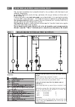
IDEA BOILERS WITH ELECTRIC IGNITION
2.5.1
The electrical installation and connection must be in accordance with the latest Local
Authority Regulations.
To simplify installation and servicing operations, all our gas boilers are fitted with a
P.C.B. TYPE A.
Connect the boiler to the electrical supply (see technical data § 1.4) ensuring that polarity
is correct (PH = phase into pole 1 - N = neutral into pole 2) and that it is earthed properly
The room thermostat should be connected between terminals No.7 and No.8 after remo-
ving the yellow-red cable bridge between them.
The time clock should be connected between terminals No.5 and No.6 after removing the
yellow-red cable bridge between them.
The terminal boards marked from No.53 to No.60 should be used to implement the
climatic controller “Micro”. Instructions for connection are detailed on the booklet
blu
blu
blu
ACC
C1
nero
nero
LR
22
PH
IG
Fus
TF
20
23
14
marrone
giallo
marrone
giallo
15
3
5
6
OR
7
A1
25
D1
12
13
4
11
18
21
17
E1
marrone
blu
blu
nero
nero
nero
nero
LPT
LF
F4
marrone
K4
Q1
TA
8
25
9
16
10
TAI
B1
25
TR
VG
L
1
N
2
OR
~
60
59
56
55
58
24
57
71
N
giallo
marrone
PR
LEGEND :
❏
❏
Terminal
➁
➁
Connection on P.C.B.
ACC
Electric igniter
FUS
Fuse
IG
Main switch
LF
Flue saftey thermostat indicator lamp
LPT
Voltage indicator lamp
LR
Heating function indicator lamp (model
PV only)
~ OR
Supply for time clock
OR
Connections for time clock
PR
Circulating pump (model PV only)
TAI
Pump overrun relay
TA
Connections for room thermostat
TF
Flue thermostat
TR
Boiler control thermostat
VG
Gas valve
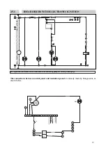
CONNECTION OF CIRCULATING PUMP (unaccessoried
models).
It can be made between terminals 11 and 13.
(should the boiler fitted with a water storage calorifier, then
follow the instructions delivered with the same).
CONNECTION OF THE PUMP OVERRUN RELAY
(OPTIONAL)
Ensure that pump has been connected between terminals 11 and
13.
After having removed the cable bridge between terminals 9
and 12, the three faston male terminals of overreun relay
should be connected as follows:
C(C)
to terminal
12
NC(1)
to terminal
10
NO(2)
to terminal
9
WARNING
The pump overrun relay TAI should have the possibility to be
setted at a temperature HIGHER than that of the boiler con-
trol thermostat TR.
11
54
53
Содержание IDEA Series
Страница 1: ...IDEA IDEAINSTALLATION A N D S ERV IC ING IN S T RU C TIONS tipo P ...
Страница 2: ......
Страница 6: ......
Страница 11: ...1 6 1 EXPLODED VIEW OF BOILER BLOCK unaccesoried version EXPLODED DRAWINGS AND PARTS LIST 1 6 5 ...
Страница 13: ...1 6 3 EXPLODED VIEW OF BOILER BLOCK accesoried version 7 ...
Страница 24: ...12010 VIGNOLO CN Via Cervasca 6 TEL 0171 407111 TELEX 226662 SARB I FAX 0171 407350 ...


