


IDEA
N. DESCRIPTION
18 PV
27 PV
36 PV
1
Flue hood
1846053
1846084
1846055
2
Ceramic rope ø 8
8567000
3
Front right side section
1830000
4
Intermediate section
1830500
5
Front left side section
1830900
6
Thermostat pocket
1764200
7
Expansion vessel
0162500
8
Manometer
8561901
9
Automatic air vent valve
1362101
10 Rubber square gasket
1866000
11 Pipe
1851600
12 Ball cock 3/4 MM mini
1391300
13 Pipe
1851900
14 Pipe
1851700
15 Safety valve 3 bar
8562100
16 Pipe
1851500
17 Blind plug
8589604
18 Circulating pump
0159306
19 Cock with cap and chain
8591201
20 Bottom rear cover plate
1845283
1845284
1845285
21 Insulating rear cover K 45
1866513
1866514
1866515
22 Base tray
1845003
1845004
1845005
23 Plate DB 1200
1892603
1892604
1892605
24 Insulating front cover K 45
1866503
1866504
1866505
25 Gas burner assembly
1855103
1855104
1855105
26 Peep-hole with sight-glass
1855060
27 Polidoro pilot burner ( T-models )
0160300
27 Ignition electrode ( T-models )
0161600
27 Thermocouple ( T-models )
0160500
27 Electrode fixing brackets ( I-models )
1848009
27 Ignition electrode ( I-models )
1861500
27 Ionisation electrode ( I-models )
1861501
28 Rubber gasket
0166301
29 Sit 820 gas valve ( T-models )
0156100
29 Sit 822 gas valve ( I-models )
1856010
30 Flange pipe
1852300
31 Gas sealing rubber gasket
1866001
32 Gasket
8566000
33 Blind plug
8589802
34 Pipe
1851800
35 Front apron
1845203
1845204
1845205
36 Tie rods
8584002
8584003
8584004
37 Black tissue felt AT 20
1880100
38 Bi-conical nipple
8589500
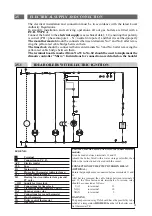
1.6.4
PARTS LIST IDEA ACCESORIED VERSION
8
Содержание IDEA Series
Страница 1: ...IDEA IDEAINSTALLATION A N D S ERV IC ING IN S T RU C TIONS tipo P ...
Страница 2: ......
Страница 6: ......
Страница 11: ...1 6 1 EXPLODED VIEW OF BOILER BLOCK unaccesoried version EXPLODED DRAWINGS AND PARTS LIST 1 6 5 ...
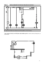
Страница 13: ...1 6 3 EXPLODED VIEW OF BOILER BLOCK accesoried version 7 ...
Страница 24: ...12010 VIGNOLO CN Via Cervasca 6 TEL 0171 407111 TELEX 226662 SARB I FAX 0171 407350 ...


