background image


9

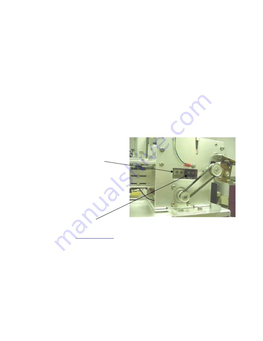
8.1.1 Load Switch and Cut Opto


There is one micro switch located below the paper guide.  This switch is used to sense the presence 
of ticket stock in the printer.  The switch is factory set and adjustment should not be necessary.   
 
The load switch should be positioned such that the printer automatically activates the stepper motor 
at the proper time when tickets are loaded into the printer.  When loading tickets, the stepper motor 
should turn on when the ticket stops in front of the thermal head.  At this point, the ticket will be 
grabbed out of your hand and fed into the printer.  
 
If the stepper motor activates without ticket stock loaded into the printer or if the ticket stock is 
properly loaded and the printer does not grab the ticket, the load switch should be adjusted.  To 
adjust the load switch, loosen the two adjustment screws and move the load switch up or down until 
the desired position is reached.  Tighten the two adjustment screws and load ticket stock to ensure 
that the load switch is properly positioned. 


ADJUSTMENT SCREWS 


LOAD SWITCH 


Click here to return to > 

Table of Contents

Содержание SUBATM

Страница 1: ...0 SUBATM MODEL TICKET PRINTER Operator s Manual Rev B 10 16 2002 ...

Страница 2: ... Paper Theory Specifications 7 8 0 Maintenance and Adjustments 8 8 1 Paper Guide and Print Head Assembly 8 8 1 1 Load Switch and Cut Opto 9 8 1 2 Thermal Print Head 10 8 1 3 Rubber Drive Roller 12 8 1 4 Ticket Width Adjustment 14 8 2 Cutter Assembly 14 8 3 Logic Board 15 8 3 1 Logic Board Removal 15 8 3 2 Logic Board Installation 16 8 4 General Cleaning 16 9 0 Spare Parts List 16 10 0 Troubleshoot...

Страница 3: ...pment when subject to normal use and service This warranty covers all parts and labor except for the print head which is warranted for 90 days All warranty labor is to be performed at the BOCA facility Equipment damaged by misuse or negligence including damage to print heads caused by defective ticket stock is excluded from this warranty Any defective equipment meeting these conditions should be r...

Страница 4: ...ming guide for additional details 2 0 Unpacking the Printer The printer is shipped in a ruggedized container Please save packing material for future use Remove the printer and accessories from the box and inspect for obvious damage If damage is noticed please report it immediately to BOCA Tel 561 998 9600 Fax 561 998 9609 The following items should be in the box a Ticket Printer b Hopper if applic...

Страница 5: ...A 6 15P 15A 250V configuration United Kingdom only The supply plug must comply with BS1363 3 pin 13 amp and be fitted with a 5A fuse which complies with BS1362 The mains cord must be HAR or BASEC marked and be of type H03VVF3GO 75 minimum Europe only The supply plug must comply with CEE 7 7 SCHUKO The mains cord must be HAR or BASEC marked and be of type H03VVF3GO 75 minimum Denmark The supply plu...

Страница 6: ...ter system You may now install the printer in its permanent location Adequate room should be provided behind or underneath the printer for the smooth feeding of ticket stock 5 0 Configuration The BOCA SubATM printer is factory configured for a variety of customer requirements For a comparison of the different electronics packages refer to the BOCA Systems website at www bocasystems com THE BASICS ...

Страница 7: ...S 5 8 CTS 20 6 DSR 20 6 DSR 6 6 DSR 6 6 DSR 20 5 CTS 20 1 CD 7 7 GND 7 5 GND 20 8 CD 20 8 CTS 8 8 CD 8 1 CD optional connection PARALLEL PIN FUNCTION 1 Strobe negative 2 9 Data DB0 DB7 10 ACK negative 11 BUSY 12 PAPER OUT 13 SELECT negative 15 ERROR negative 18 Ground RS422 DIFFERENTIAL INTERFACE PINOUTS 422190 9 FAA LOR PIN FUNCTION PIN FUNCTION 1 7 Ground 1 7 Ground 19 Printer Transmit 19 Printe...

Страница 8: ...eases will seriously exponentially degrade the head life The thermal paper can affect the electrical head life in two ways Insensitive slow papers will typically encourage the user to increase the voltage to darken the printed image This will directly increase the head temperature resulting in reduced head life Additionally the higher temperatures will frequently cause the ink to peel off the tick...

Страница 9: ...oard assembly As a safety precaution all service to the printer should be done by qualified persons with power off and the AC cord unplugged from the printer Following any procedure requiring the removal of covers and or doors please verify that they have been properly attached and fastened prior to operating the printer 8 1 Paper Guide and Print Head Assembly The principal function of this assemb...

Страница 10: ... when the ticket stops in front of the thermal head At this point the ticket will be grabbed out of your hand and fed into the printer If the stepper motor activates without ticket stock loaded into the printer or if the ticket stock is properly loaded and the printer does not grab the ticket the load switch should be adjusted To adjust the load switch loosen the two adjustment screws and move the...

Страница 11: ...uld cut the ticket just behind the perforation The ticket should never be cut in front of the perforation If you are not able to get the desired cut position make sure your ticket stock was manufactured to proper specifications For major adjustments loosen the two adjustment screws Slide the opto forward or back on the opto bracket until the desired cut position is achieved Tighten the adjustment ...

Страница 12: ...UG CABLE FROM PRINT HEAD 3 Lift up on the cam lock assembly located above the head mounting block to remove pressure from the thermal head 4 Lift up on the head mounting block thermal head to remove 5 Clean the thermal print head surface the side that makes contact with the paper with isopropyl alcohol 6 Install the head by reversing the above procedures 7 Restore pressure to the head by pushing d...

Страница 13: ...Restore pressure to the head by closing the red handled lever 8 1 3 Rubber Drive Roller Platen The rubber drive roller should be cleaned once a year to prevent paper dust from building up on the roller Clean drive roller with a paper towel and alcohol 1 Unlock the thermal head and tilt back to gain access to platen 2 Clean the full length of the platen 3 Rotate the platen clockwise and repeat step...

Страница 14: ... special head setting on the control panel must be used to load the new ticket width into the printer s memory No control panel adjustment is necessary on standard adjustable printers ADJ If the printer lacks a control panel the width adjustment can be made through software see the programming guide for both control panel and software adjustments Note The ticket should move freely in the paper gui...

Страница 15: ...k into the printer after power up During this time the SC2 will rotate once If ticket stock is fed into the printer before five seconds a ticket jam could occur The SC2 should be blown out with air periodically to prevent debris from building up inside the cutter area The required cleaning interval varies greatly depending on the quality of the ticket stock and the amount of paper dust entering th...

Страница 16: ...required Warning ALL SERVICE SHOULD BE DONE WITH POWER OFF AND THE AC CORD UNPLUGGED FROM THE PRINTER See below picture for main logic board access 8 3 1 Logic Board Removal 1 Gain access to the logic board 2 Unplug connectors going to the main logic board 3 Remove the nuts that secure the heat sink to the cabinet 4 Use a screwdriver to gently wedge the logic board from the fasteners 5 Lift board ...

Страница 17: ...03 ANTI STATIC BRUSH WITH MTG BRACKET 3 25 422226 3 BEZEL FEED 3 25 VM AMC paper guide 422819 BURSTER ASSY Mag Mini 423226 20 CABLE RIBBON CONTROL PANEL 20 FLG 22 42 423123 CABLE RIBBON DATA CABLE PARALLEL for FGL 22 42 423124 CABLE RIBBON DATA CABLE SERIAL for FGL 22 42 422557 16 CABLE RIBBON THERMAL HEAD 3 25 4 0 16 422557 18 CABLE RIBBON THERMAL HEAD 3 25 4 0 18 422558 16 CABLE RIBBON THERMAL H...

Страница 18: ...2006 1 HOLD DOWN PLATE FOR 4 00 FLIP UP DOOR P40 1012 HOLD DOWN PLATE SCREW 421623 HOPPER SINGLE Printer Dependent MAX234 IC MAX 421164 1 IDLER ARM EJECT 431010 IDLER ARM EJECT WHEEL 422920 1 INTERFACE BOARD PARALLEL for FGL 22 42 422920 PC INTERFACE BOARD PC serial for FGL 22 42 422920 6 INTERFACE BOARD SERIAL std for FGL 22 42 KN 500B KNOB DRIVE ROLLER ASSY P49 1009 LATCH POST CABINET MINI PLUS ...

Страница 19: ...DEFECTOR UPPER 2 422710W SILENT CUTTER ENTRANCE DEFECTOR UPPER 3 35 4 P28 1015 SILENT CUTTER MICRO SWITCH P33 1006 SILENT CUTTER MOTOR ONLY 422810 SILENT CUTTER MOTOR GEAR BOX ONLY 422371 1 SILENT CUTTER MOTOR PINION GEAR 420816 SC2 SILENT CUTTER MTG BRACKET 2 wide paper path 420816 WSC2 SILENT CUTTER MTG BRACKET 3 25 wide paper path 420816 5M4 SILENT CUTTER MTG BRACKET 4 0 wide paper path P44 101...

Страница 20: ...the printer b If cutter motor does not rotate after power up See 6 c Unplug the thermal head and turn on the printer If printer works replace the thermal head d Replace the Main logic board 3 POWER IS ON BUT TICKET WILL NOT LOAD a See 2 b Make sure the print head cam lock assembly is fully locked in the closed position Consult Thermal Print Head section c Check that the ticket stock is being loade...

Страница 21: ...d cable for electrical connection at both ends b Check to make sure head cable is plugged in properly into the thermal head c Replace the thermal head d Replace the Main logic board 10 PRINTER SKIPS TICKETS WHILE PRINTING a Check all electrical connections on the printer b Check position and quality of black mark on the ticket stock c Clean off opto eyes Consult Load Switch and Cut Opto section d ...

Страница 22: ...ng on the topic you wish to change 4 Press CHOICES to scroll through choices in the selected topic NOTE The printer displays a blinking cursor for the values presently stored in the printer 5 Once you have found the new value you want press TEST The LCD window displays EXIT AND SAVE If you wish to save the new value then press TEST again 6 If you do not wish to save the new value then press MENU T...

Страница 23: ...et entrance area Cut counts are increments of 003 for 300dpi and 005 for 200dpi Depressing CHOICES changes the count value 16 is factory default 1 is for path one 2 is for path 2 dual only DEC CUT1 2 COUNT moves the cut tear position to the right towards the ticket exit area Cut counts are decrements of 003 for 300dpi and 005 for 200dpi Depressing CHOICES changes the count value 16 is factory defa...

Отзывы: