background image


Mod.BM43 

COM 

Vers.1.0 

16/11/2005 

Page 15 of 

110


P i p e   O u t e r   P e r i m e t e r  

>  

7 0 _    


m m  

Press 

 2 times: 

P i p e   O u t e r   P e r i m e t e r  

>  

7 2 _    


m m  

Press 

 1 time and the unit will display: 

P i p e   O u t e r   P e r i m e t e r  

>  

7 2 0 _   


m m  


Press 

 5 times: 

P i p e   O u t e r   P e r i m e t e r  

>  

7 2 5 _   


m m  

Than press

, now the unit will display: 

P i p e   O u t e r   P e r i m e t e r  


7 2 5   m m  

Using the 


keys it’s possible to enter all 

the digits you need to program the TTFM100-F18-NG. 

The 

 and 

 keys are used to scroll the menu up or down. 


Содержание TTFM100-F18-NG

Страница 1: ...Mod BM43 COM Vers 1 0 16 11 2005 Page 1 of 110 ULTRASONIC TRANSIT TIME FLOWMETER TTFM100 F18 NG STATIONARY TYPE INSTRUCTION MANUAL Rev 2 0 ...

Страница 2: ...3 DISPLAY WINDOWS 38 3 1 FLOW RATE TOTALIZERS MENU 38 3 2 INITIAL SETTING MENU 38 3 3 FLOWRATE UNITS MENU 39 3 4 OPTIONAL SETTING MENU 39 3 5 INPUTS OUTPUTS MENU 39 3 6 DIAGNOSTICS MENU 41 3 7 OTHER DISPLAY MENU 41 3 8 FLOW RATE TOTALIZERS MENU ANALYSIS 41 3 9 INITIAL SETTINGS MENU ANALYSIS 43 3 10 FLOWRATE UNITS MENU ANALYSIS 50 3 10 1 Inputs Outputs Menu Analysis 56 3 11 DIAGNOSTICS MENU ANALYSI...

Страница 3: ...used to measure the flow rate of homogeneous fluids with a very little percentage of suspended solids and possibly without gas bubbles Its peculiar installation makes these devices suitable for measuring aggressive fluids acids basic and dissolvent or very soiling fluids oil and fuels The measuring system is composed of a couple of ultrasonic transducers acoustically coupled to the external pipe s...

Страница 4: ...the flow speed see the following picture The measures are taken by 2 sensors in direct contact with the pipe s external surface The UP sensor RED is placed on the upper side of the pipe s external surface the DOWN sensor BLUE is placed on the lower side of the pipe s external surface The sensors positions could look like a Z or like a V or a W if the pipe has a small diameter in the previous sketc...

Страница 5: ...ors which make the precision decrease for example the dumps on the pipe are internal walls they change the measuring principle of the transit time flow meter TTFM100 series has are a lot of solutions trying to solve these problems compensating the temperature influence the dumped internal walls and the asymmetry in the speed distribution in order to measure in critical conditions too It is possibl...

Страница 6: ...ual 1pcs DEPENDING FROM THE TYPE OF SENSORS ORDERED BY THE CUSTOMER TECHNICAL FEATURES ITEM PERFORMANCE PIPE Material Internal Diameter Pipe length Steel Stainless Steel cast iron plastic with smooth walls with rough walls with very thin walls 15 6000 mm Upstream bigger than 10D and 30D far from the pump downstream bigger than 5D FLUID Type Turbidity Temperature Potable water sea water other liqui...

Страница 7: ...ods V Method for pipes with small diameter until DN400 mm Z Method for pipes with big diameters bigger than DN250 W or N Method suitable for very small pipes DN15 100 FLOWMETER Display Keypad Mounting Input Outputs Dimensions Alphanumeric 2 x 20 digits LCD back lighted DIN Rail Mounting 5 current loop 4 20 mA 0 1 accuracy Selection 4 20 mA or 0 20 mA current loop 0 1 accuracy Serial port RS485 Pro...

Страница 8: ...5 Page 8 of 110 Repeatability 0 2 0 5 at 0 6 16mt s Linearity 0 5 Min measuring cycle 500 milliseconds POWER SUPPLY 12 36VDC 0 12A Attention Negative connector common with negative 0 4 20 mA output FUNCTIONING Continuous 1 2 1 Wiring ...

Страница 9: ...Mod BM43 COM Vers 1 0 16 11 2005 Page 9 of 110 1 2 2 Connections The kind of connection and the number of connections both depend from the application the flow meter is used for ...

Страница 10: ...er to download the electrostatic fields generated during the sensors movement The crystal inside the transducer acts as a converter and turns mechanical energy into electrical during the mounting process When the sensors are connected to the clamp house the electrostatic fields into the capacitor could damage seriously the measuring circuit of the device 4 20 ma output and or frequency and or puls...

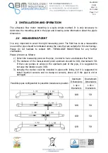
Страница 11: ... M TECNOLOGIE INDUSTRIALI for any further clarification Please proceed as follows 1 Select the measuring point on the pipe in order to have a turbulence free fluid 2 The distance of the measurement point upstream should be 10D downstream 5D If there are pumps or valves in the upstream part of the pipe it is suggested to increase the distance up to 30 D 3 Actually the device could be installed in p...

Страница 12: ... 3 Pipe s material or speed of sound through that material 4 Internal liner if existing material or thickness or speed of sound through that material 5 Fluid type or speed of sound through this fluid 6 Transducers type 7 Transducer mounting method V Z method or W N for little pipes Now in M25 menu it is be possible to see the right mounting distance between the transducers ...

Страница 13: ...LY GOES OFF 2 3 1 Fluid pipe s features This is a zinc pipe so its thickness is not a problem It is also important to measure the pipe s circumference it should be 1286 mm The pipe is PN10 and it will measure potable water 2 3 2 Data entry ATTENTION The XXXXX values indicated in the following windows are only examples The value could vary and must not be taken as representative TTFM100 F18 NG how ...

Страница 14: ...e key the display will be F l o w 0 0 0 0 0 m 3 h R W i n d o w N o 1 0 By pressing the key we will access MENU 10 Pipe Outer Perimeter P i p e O u t e r P e r i m e t e r x x x x x x x m m Now we want to enter 725 mm to set up our application Press the key and the display will show P i p e O u t e r P e r i m e t e r _ m m Using the and keys you can change the display value Press 7 times and the ...

Страница 15: ...me and the unit will display P i p e O u t e r P e r i m e t e r 7 2 0 _ m m Press 5 times P i p e O u t e r P e r i m e t e r 7 2 5 _ m m Than press now the unit will display P i p e O u t e r P e r i m e t e r 7 2 5 m m Using the keys it s possible to enter all the digits you need to program the TTFM100 F18 NG The and keys are used to scroll the menu up or down ...

Страница 16: ...ast switch off for example Flow 0 0000 m3 h I No Signal Detected The transducers are not installed and their mounting distance will be displayed only after the set up Actually the device detects no signals Press MENU and the device will display Flow 0 0000 m3 h I Window No Press 1 0 and the device will display window no 10 Pipe Outer Perimeter XXXX mm Press 1 2 8 6 and ENT ...

Страница 17: ...m Press and the device will display Pipe Wall Thickness X X mm Press 6 5 ENT and the it will display Pipe Wall Thickness 6 5 mm Press and the device will display Pipe Inner Diameter 396 347 mm The device calculates the value based on the entered settings It is possible to press again and the device will display the parameters it calculated until now Press and the device will display ...

Страница 18: ...Material 14 0 Carbon Steel Press ENT and and the device will display Liner Material 16 0 None No Liner In this case the pipe has no internal lining so 0 is correct Press and the device will display Fluid Type 20 0 Water General Press and the device will display Transducer Type 23 16 Clamp on TM1 NOTE The standard sensors are Clamp on TM1 type for pipes from DN50 up to DN1000 It is possible to ask ...

Страница 19: ...n in par 2 2 It is possible to install the transducers as shown in the following par 2 4 Press and the device will display Default settings 26 1 Solidify settings Press and the device will display Save Load parameters Press to go through the parameters Save Load parameters To Browse Press and the device will display Save Load parameters 0 409 347 mm Carbon This setting refers to the example config...

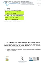
Страница 20: ...ow it is possible to install the transducers 2 4 INSTRUCTIONS FOR CLAMP ON SENSORS INSTALLATION If you ordered Clamp on sensors type TTS100 TS2 NG TTS100 M1 NG TTS100 L1 NG TTS100 S1 NG HT TTS100 M1 NG HT the following instructions are very important for a correct installation of the sensors 1 In order to install the sensors check if the pipe has features which could affect the measure i e rust di...

Страница 21: ...Mod BM43 COM Vers 1 0 16 11 2005 Page 21 of 110 2 Measure the pipes diameter by using a callipers ...

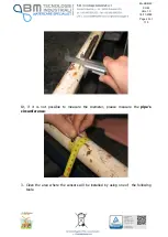
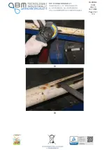
Страница 22: ... Vers 1 0 16 11 2005 Page 22 of 110 Or if it is not possible to measure the diameter please measure the pipe s circumference 3 Clean the area where the sensors will be installed by using one of the following tools ...

Страница 23: ...Mod BM43 COM Vers 1 0 16 11 2005 Page 23 of 110 Or Or ...

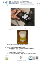
Страница 24: ...M Vers 1 0 16 11 2005 Page 24 of 110 4 The pipe section where the sensors will be installed should be completely clean 5 Measure the pipe s thickness This could be done by using our Thickness Gauge TT100 TM8812 NG ...

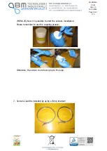
Страница 25: ...ease Otherwise the sensors could loose the grip to the pipe 6 Enter the following values into device s menus pipe s diameter MENU 11 or pipe s circumference MENU 10 pipe s thickness MENU 12 type of sensors to be used MENU 23 Sensors mounting method MENU 24 The device will display the distance at which the sensors should be installed ...

Страница 26: ... 2005 Page 26 of 110 MENU 25 Now it is possible to start the sensors installation Please remember to use the coupling grease Otherwise the sensor could loose grip to the pipe 7 Sensors could be installed by using a fixing bracket ...

Страница 27: ...l Guide Mounting System RGMS TS2 TM1 NG FIX only with TS2 TM1 sensors pipes form DN15 to DN300 8 Install the sensors according to the distance value the device displays in MENU 25 a Installation of the clamp on sensors with the fixing brackets Installation is completed ...

Страница 28: ...COM Vers 1 0 16 11 2005 Page 28 of 110 b Installation of the clamp on sensors with our Rail Guide Mounting System RGMS TS2 TM1 NG FIX only with TS2 TM1 sensors pipes form DN15 to DN300 Installation is completed ...

Страница 29: ... another Z one crossing Suitable for pipes DN250 mm or smaller V two crossings It is the easiest mounting method for DN600 800 pipes with TL 1 or TM 1 transducers N three crossings Suitable for small pipes DN100 or smaller with TS 2 transducers It similar to Z method but for small pipes In this case the mounting distance will be bigger W four crossings Suitable for DN20 pipes with TS 2 transducers...

Страница 30: ...Mod BM43 COM Vers 1 0 16 11 2005 Page 30 of 110 V mounting method N mounting method ...

Страница 31: ...60 see MENU 90 Strenth Quality 90 UP 54 4 DN 56 5 Q 45 A V mounting Use 2 4 to set the V mounting method The V method uses a bounce into the pipe and the ultrasonic wave goes through more distance The measuring principle is based on the difference of time and through a V distance the time needed is bigger and the precision higher In case of horizontal mounting it is suggested to avoid mounting the...

Страница 32: ... lining such as tar polyethylene epoxy should be cleaned when in contact with the transducers A tube for acoustic coupling paste or grease is included in the supply Use a small quantity of coupling grease in order to improve acoustic the contact between the sensor and the pipe s external surface B Z method In 2 4 select the option 1 if you want to choose Z mounting T r a s d u c e r M o u n t i n ...

Страница 33: ... paper to wrap the pipe Please refer to the picture below for finding the two lines needed to trace the exact half point of the pipe Once the band was fixed on the circumference of the tube with adhesive tape it is possible to fix the sensors as shown in the picture If the pipe is horizontally mounted it is suggested to mount the sensors as shown in the next picture If the pipe is vertically mount...

Страница 34: ... four crossings for W method and three crossings for N method inside the pipe These methods are used to increase the transit and receiving time because in other ways the signal path in small pipes will be too short In W method the sensors are placed on the same side of the pipe distance in menu 25 In N method the sensor are placed on the opposite sides of the pipe distance in menu 25 ...

Страница 35: ...Mod BM43 COM Vers 1 0 16 11 2005 Page 35 of 110 These methods are not very used because even TS2 NG PTTFM2000 small sensors could be mounted by using Z method ...

Страница 36: ... the signal is the worst 99 9 mean signal is the best In normal working conditions the signal quality should be higher than 60 0 During installation please pay attention to signal strength and quality they should be at the maximum level 2 5 3 Total spreading time time difference M93 Digit MENU 9 3 Total Time Delta Time 623 80uS 242 12nS The measurement method is based on time difference so the tim...

Страница 37: ...en calculated and measured transit time To know if the sensors are correctly installed the user should calculate 100 _ TOS TOM Rate Time In standard working conditions it should be 100 3 Digit MENU 9 1 TOM TOS 100 91 100 25 And eventually check the right mounting method ...

Страница 38: ...Flow Rate POS Totalize 03 Flow Rate NEG Totalize 04 Date Time Flow Rate 05 Energy Flow Rate Totalize 06 T1 T2 07 AI3 AI4 Input 08 System Error Code 09 Net Flow Today 3 2 INITIAL SETTING MENU 10 Pipe Outer Perimeter 11 Pipe Outer Diameter 12 Pipe Wall Thickness 13 Pipe Inner Diameter 14 Pipe Material 15 Pipe Sound Velocity 16 Liner Material 17 Liner Sound Velocity if in menu 16 the user chooses oth...

Страница 39: ... Rate Units 32 Totalizer Units 33 Totalizer Multiplier 34 NET Totalize 35 POS Totalize 36 NEG Totalize 37 Totalizer Reset 38 Manual Totalizer 39 Language Selection 3 4 OPTIONAL SETTING MENU 40 Damping 41 Low Flow Cutoff 42 Set Zero 43 Reset Zero 44 Manual Zero Point 45 Scale Factor 46 Network IDN 47 System Lock 48 Entry to calibration data 49 Serial Port traffic 3 5 INPUTS OUTPUTS MENU 50 Data Log...

Страница 40: ...e 65 AI4 Value Range 66 AI5 Value Range 67 FO Frequency Range 68 Low FO Flow Rate 69 High FO Flow Rate 70 LCD Backlight Option 71 LCD Contrast 72 Working Timer 73 Alarm 1 Low Value 74 Alarm 1 High Value 75 Alarm 2 Low Value 76 Alarm 2 High Value 77 Beeper Setup 78 OCT Output Setup 79 Relay Output Setup 80 Batch trigger select 81 Flow Batch Controller 82 Date Totalizer 83 Automatic Amending 84 Ener...

Страница 41: ...velocity Threshold 2 Last Power off Time 7 Total flow for month 3 Last Flow Rate 8 Total flow this year 4 ON OFF Times 9 Timer 3 8 FLOW RATE TOTALIZERS MENU ANALYSIS Digit MENU 0 0 and the device will display F l o w 1 2 3 0 0 m 3 h R N E T 3 4 5 2 x 1 m 3 This is only a display window Values cannot be changed NET is the net totalizer result of adding the positive totalizer POS to the negative tot...

Страница 42: ...8 1 2 0 9 5 4 0 0 R F l o w 1 2 3 0 0 m 3 h This window displays date and time in the following format yy mm dd hh mm ss and the current flow rate Date and time should be set up in menu M60 Digit MENU 0 5 and the device will display E F R 0 0 0 0 0 G J h R E T 0 E 0 G J This window displays the energy flow and the totalized energy Pls refer to the part of the manual explaining energy measurements ...

Страница 43: ...INITIAL SETTINGS MENU ANALYSIS Digit MENU 1 0 and the device will display P i p e O u t e r P e r i m e t e r 1 2 8 6 m m This window is used to set up the pipe s perimeter if it is known or measurable Digit MENU 1 1 and the device will display P i p e O u t e r D i a m e t e r 4 0 9 3 4 7 m m This window is used to set up the external pipe s perimeter When the external perimeter is set up the ext...

Страница 44: ...n steel 1 stainless steel 2 cast iron 3 ductile iron 4 copper 5 PVC 6 aluminum 7 asbestos 8 fiberglass epoxy 9 other For information about the sound speed in other types of material that are not included in the list please refer to the tables starting at page 89 If in MENU 1 4 you chose 9 other digit MENU 1 5 and the device will display P i p e S o u n d V e l o c i t y x x x x m s Set up the soun...

Страница 45: ...the sound speed in other types of material that are not included in the list please refer to the tables starting at page 89 This Menu will activate only if in M16 the user chose 11 OTHER Digit MENU 1 7 and the device will display L i n e r S o u n d V e l o c i t y x x x x m s Set up the spreading time of sound through the construction material of the liner For information about the sound speed in...

Страница 46: ...W a t e r This window is used to set up the type of fluid Press ENT to enable the fluid selection and use the arrow keys to scroll the list 0 water general 1 sea water 2 kerosene 3 gasoline 4 fuel oil 5 crude oil 6 propane 45 C 7 butane 0 C 8 other liquid 9 diesel oil 10 castor oil 11 peanut oil 12 gasoline 90 13 gasoline 93 14 alcohol 15 water 125C Press ENT to confirm For information about the s...

Страница 47: ... display F l u i d V i s c o s i t y 2 2 1 0 0 3 8 c S T Set up the viscosity of the fluid to be measured Digit MENU 2 3 and the device will display T r a n s d u c e r T y p e 2 3 0 S t a n d a r d M This window is used to set up the type of transducers Press ENT to enable the transducers type selection and use the arrow keys to scroll the list 0 Standard M 1 Insertion type C 2 Standard S 3 User ...

Страница 48: ...res of the new type of sensors 1 Wedge degree of ultrasonic impulse W e d g e D e g r e e 4 5 d e g 2 Spreading time through sensor W e d g e S o u n d V e l o c i t y 2 7 2 0 m s 3 Distance from crystal to sensor wedge W e d g e D i s t a n c e 3 2 m m 4 Delay of ultrasonic signal W e d g e T i m e D e l a y 5 1 8 u S Digit MENU 2 4 and the device will display T r a n s d u c e r M o u n t i n g ...

Страница 49: ... IMPORTANT WHEN THE SET UP PROCEDURE IS COMPLETED SELECT THE OPTION 1 SOLIDIFY SETTINGS PARAMETERS WILL BE SAVED EVEN IF THE POWER SUPPLY GOES OFF Digit MENU 2 6 and the device will display D e f a u l t s e t t i n g s 1 S o l i d i f y s e t t i n g s Press ENT and then use the arrow keys to select among D e f a u l t S e t t i n g s 0 U s e R A M s e t t i n g s This window allows to upload one...

Страница 50: ...ain the last reading as valid in case of temporary loss of signal If NO is selected output signal could be modified Digit MENU 2 9 and the device will display E m p t y P i p e S e t u p 2 9 4 0 This window is used to set up a min threshold Below that threshold the device considers the pipe as empty Set up a value among 30 and 40 in order to be sure the device does not measure when the pipe is emp...

Страница 51: ...o u r Use the arrow keys to select the time units to which the current flow rate should refer hour day min sec Press ENT to confirm the selection Digit MENU 3 2 and the it will display T o t a l i z e r U n i t s 3 2 C u b i c M e t e r s m 3 This window is used to set up totalizing flow rate units please refer to menu M31 for what concerns Volumetric units and their settings Factory settings are ...

Страница 52: ...g is ON Press ENT and then use the arrow keys to select ON or OFF Press ENT to confirm Digit MENU 3 5 and the it will display P O S T o t a l i z e r 3 5 O N This window is used to enable the positive totalizer Factory setting is ON Press ENT and then use the arrow keys to select ON or OFF Press ENT to confirm Digit MENU 3 6 and the it will display N E G T o t a l i z e r 3 6 O N This window is us...

Страница 53: ...s selected the device will display S e l e c t T o t a l i z e r choose among the following options k None l All m NET Totalizer n POS Totalizer o NEG Totalizer p Energy NET Totalizer q Energy POS Totalizer r Energy NEG Totalizer s Master Erase t Net Flow Today Master Erase WARNING THIS OPTION WILL RESET ALL THE SETTINGS DO NOT CONFIRM Press ENT to confirm the selection and the device will display...

Страница 54: ...lish Press ENT and then use the arrow keys to select the language Press ENT to confirm Digit MENU 4 0 and the it will display D a m p i n g 4 0 1 5 s e c Ita is possible to change the value of damping the seconds the device needs to display the analog signals and the output signals The standard value is between 15 and 30 seconds the setting range goes from 0 to 99 seconds Digit MENU 4 1 and the it...

Страница 55: ...ocedure of the previous menu M42 Press ENT and then use the arrow keys to display NO or YES to disable or enable the deleting function Digit MENU 4 4 and the it will display M a n u a l Z e r o P o i n t 4 4 0 m 3 h This window is used for setting an offset value to be added or detracted it depends from the setting polarity to the current flow rate If the user knows very well the current flow rate...

Страница 56: ...t e m L o c k 4 7 U n l o c k e d This window is used to set up a password to prevent the system from unauthorized access It is composed of a number from 1 up to 4 digits Digit MENU 4 8 and the it will display E n t r y t o c a l i b r a t i o n d a t a 4 8 E n t r y This window is used for calibration purposes Digit MENU 4 9 and the it will display S e r i a l p o r t t r a f f i c 4 9 x x x x x ...

Страница 57: ... d T o R S 4 8 5 It is possible to send data to Internal serial BUS SDI Serial Data Interface RS485 If you choose this option go to menu M63 for additional information Digit MENU 5 3 and the it will display A n a l o g I n p u t A I 5 5 3 A I 5 0 0 2 3 4 2 4 9 8 6 This window displays the status of AI5 current input referring to the conversion in measuring units Digit MENU 5 4 and the it will disp...

Страница 58: ...ring flow rate value Press ENT and then digit the flow rate minimum range value for example 0 m3 h if flow rate will be measured in m3 Press ENT again to confirm Digit MENU 5 7 and the it will display C L 2 0 m A O u t p u t V a l u e 5 0 0 m 3 h This window is used to set up the maximum range of the output signal for a determined measuring flow rate value Press ENT and then digit the flow rate ma...

Страница 59: ... e n R e a d y Press ENT again and the device will display A O C a l i b r a t i o n M 1 4 m A 9 8 8 2 2 It is suggested to take note of the displayed value before changing it Press the arrow keys and you will be able to change the value it is also possible to digit it directly When changed press ENT again and the device will display A O C a l i b r a t i o n M 1 2 0 m A 5 0 1 1 2 It is suggested ...

Страница 60: ...nal and the settings in M55 Digit MENU 6 0 and the device will display Y Y M M D D H H M M S S 0 9 1 0 0 5 0 9 5 4 2 6 This window is used to set up date and time Press ENT and digit year month day of the month hour minute and seconds Press ENT again to confirm If during the set up the user makes a mistake or if it is necessary to change a value press the key until you reach the desired digit and ...

Страница 61: ... type among None Even Odd Press ENT to confirm the selection and exit the setting The other parameters are factory set up 8 bit data 1 bit stop and flow control Xon Xoff Digit MENU 6 3 and the device will display S e l e c t c o m m p r o t o c o l M O D B U S A S C I I T D S 7 This window is used to set up the communication protocol Select between x MODBUS RTU If you choose this option you should...

Страница 62: ...s V a l u e 1 0 0 Digit the ending value and press the key The setting is finished Digit MENU 6 5 and the device will display A I 4 V a l u e R a n g e 6 5 0 1 0 0 This window is used to set up the conversion into measuring units of 4 20 mA input of analog input 4 Press ENT and the device will display A I 4 4 m A v s V a l u e 0 Digit the starting value and press ENT then press the key and the dev...

Страница 63: ...he key The setting is finished Digit MENU 6 7 and the device will display F O F r e q u e n c y R a n g e 0 9 9 9 9 This window is used to set up the frequency output the range is 0 9999 Hz proportional to the measured flow rate Press ENT and key The device will display L o w F O F r e q u e n c y 0 Digit the starting value and press ENT then press the key and the device will display H i g h F O F...

Страница 64: ...ress ENT digit the value in measuring units and press ENT again Digit MENU 7 0 and the device will display L C D B a c k l i t O p t i o n 1 A l w a y s O N This window is used to set up the display backlight Press ENT and then use the arrow keys to enter the seconds if you select 60 and press ENT it will display L C D B a c k l i t O p t i o n 6 0 s e c Digit MENU 7 1 and the device will display ...

Страница 65: ...ENU 7 4 and the device will display A l a r m 1 H i g h V a l u e 5 0 0 m 3 h This window is used to set up the maximum flow rate threshold for alarm 1 press ENT digit the flow rate value and press ENT again Digit MENU 7 5 and the device will display A l a r m 2 L o w V a l u e 0 m 3 h This window is used to set up the minimum flow rate threshold for alarm 2 press ENT digit the flow rate value and...

Страница 66: ...m 1 7 Reverse Alarm 2 8 Batch Controller 9 POS Int Pulse 10 NEG Int Pulse 11 NET Int Pulse 12 Energy POS Pulse 13 Energy NEG Pulse 14 Energy NET Pulse 15 Upper Threshold Velocity MediaVel Thresh 16 Lower Threshold Velocity MediaVelo Thresh 17 ON OFF via RS485 18 Timer M51 Daily 19 Timed Alarm 1 20 Timed Alarm 2 21 Batch Total Full 22 Timer by M51 23 Batch 90 full 24 Key Stroking ON 25 Disable BEEP...

Страница 67: ... 100 5 FO over 120 6 Alarm 1 7 Reverse Alarm 2 8 Batch Controller 9 POS Int Pulse 10 NEG Int Pulse 11 NET Int Pulse 12 Energy POS Pulse 13 Energy NEG Pulse 14 Energy NET Pulse 15 Upper Threshold Velocity MediaVel Thresh 16 Lower Threshold Velocity MediaVelo Thresh 17 ON OFF via RS485 18 Timer M51 Daily 19 Timed Alarm 1 20 Timed Alarm 2 21 Batch Total Full 22 Timer by M51 23 Batch 90 Full 24 Flow R...

Страница 68: ...rval 11 NET pulse interval 12 Energy POS pulse 13 Energy NEG pulse 14 Energy NET pulse 15 Upper Threshold Velocity MediaVel Thresh 16 Lower Threshold Velocity MediaVelo Thresh 17 ON OFF via RS485 18 Timer M51 Daily 19 Timed Alarm 1 20 Timed Alarm 2 21 Batch Total Full 22 Timer by M51 23 Batch 90 Full 24 Disable Relay Press ENT again to confirm the selection Digit MENU 8 0 and the device will displ...

Страница 69: ...in The device will display F l o w B a t c h C o n t r o l l e r If in menu M80 you selected 0 key Input by pressing ENT the device will display 1 0 0 0 m 3 O N 0 m 3 If ON is blinking the counter m3 will increase the value until the BATCH volume is reached The programmed output for this function will change its status If you press ENT before reaching the BATCH value the function will stop Digit M...

Страница 70: ...a t i c A m e n d i n g O F F This window is used to enable the automatic correction of all the totalizers when the device is switched off The average value before switching off the device and just after switching on the device is used to calculate the volume of flow Press ENT and then use the arrow keys to display ON or OFF to enable or disable this function Press ENT again to confirm the selecti...

Страница 71: ... related to the energy measurement Digit MENU 8 7 and the device will display E n e r g y T o t l e r O N O F F O N This window is used to enable the energy totalization Press ENT and the use the arrow keys to display ON or OFF to enable or to disable this function Press ENT to confirm the selection Digit MENU 8 8 and the device will display E n e r g y M u l t i p l i e r 8 8 4 x 1 E 0 This windo...

Страница 72: ...9 and the device will display T e m p e r a t u r e D i f f 8 9 0 0 0 0 0 C This window is used to set up the temperature differential ΔT Press and the device will display H e a t M e t e r I s O n 8 1 I n l e t Set the Heater measurement system 0 Outlet 1 Inlet Press ENT to confirm the selection ...

Страница 73: ...cate an error in mounting or the setting of wrong parameters Digit MENU 9 2 and the device will display F l u i d S o u n d V e l o c i t y 1 4 8 2 5 6 m s This window displays the speed of sound through the fluid In normal working conditions the value should be similar to the one indicated in menu M21 Big differences indicate an error during the sensors mounting or an error in M21 Digit MENU 9 3 ...

Страница 74: ...will display P o w e r O N O F F T i m e 0 P r e s s E N T W h e n R e a d y The device has been switched ON OFF in a determined date and time Press ENT and then use the arrow keys to display the sequence of 64 events from 00 up to 63 of switching on and switching off Press the key to display T o t a l W o r k H o u r s 1 0 0 0 0 0 1 3 5 3 4 4 5 Press the key to display L a s t P o w e r O f f T i...

Страница 75: ...nd then Y value Press ENT to calculate Press the key to display M e d i a v e l o c i t y T h r e s h o l d 1 m s This value is used as a threshold to generate an alarm on the relay or on they OCT when it has been passed Press the key to display T o t a l f l o w f o r m o n t h Press the key to display T o t a l f l o w t h i s y e a r Press the key to display N o r e a d y t i m e r ...

Страница 76: ...ontact B M Tecnologie Industriali STORED DATA ERROR Digit ENT again during the initial set up up HAND SHAKING ERR Switch off and then switch on CPU FATAL ERROR Contact B M Tecnologie Industriali TIMER SLOW ERROR TIMER FAST ERROR Switch off and then switch on or contact B M Tecnologie Industriali SYSTEM RAM ERROR Switch off and then switch on or contact B M Tecnologie Industriali TIME OR BATT ERROR...

Страница 77: ...ality signal Poor signal quality SEE ABOVE Q Freq output power Output frequency bigger than 120 very high flow rate or wrong settings Check again the settings in M66 and in M69 or simply confirm that the flow rate should be so big E Over current loop Output current bigger than 100 very high flow rate or wrong settings Check again the settings in M66 or simply confirm that the flow rate should be s...

Страница 78: ...Mod BM43 COM Vers 1 0 16 11 2005 Page 78 of 110 ...

Страница 79: ...Mod BM43 COM Vers 1 0 16 11 2005 Page 79 of 110 ...

Страница 80: ...Mod BM43 COM Vers 1 0 16 11 2005 Page 80 of 110 5 2 SOUND SPEEDS IN FLUIDS ...

Страница 81: ...Mod BM43 COM Vers 1 0 16 11 2005 Page 81 of 110 ...

Страница 82: ...Mod BM43 COM Vers 1 0 16 11 2005 Page 82 of 110 ...

Страница 83: ...Mod BM43 COM Vers 1 0 16 11 2005 Page 83 of 110 ...

Страница 84: ...Mod BM43 COM Vers 1 0 16 11 2005 Page 84 of 110 ...

Страница 85: ...Mod BM43 COM Vers 1 0 16 11 2005 Page 85 of 110 ...

Страница 86: ...Mod BM43 COM Vers 1 0 16 11 2005 Page 86 of 110 ...

Страница 87: ...Mod BM43 COM Vers 1 0 16 11 2005 Page 87 of 110 ...

Страница 88: ...Mod BM43 COM Vers 1 0 16 11 2005 Page 88 of 110 ...

Страница 89: ...Mod BM43 COM Vers 1 0 16 11 2005 Page 89 of 110 ...

Страница 90: ...Mod BM43 COM Vers 1 0 16 11 2005 Page 90 of 110 ...

Страница 91: ...Mod BM43 COM Vers 1 0 16 11 2005 Page 91 of 110 ...

Страница 92: ...Mod BM43 COM Vers 1 0 16 11 2005 Page 92 of 110 ...

Страница 93: ...Mod BM43 COM Vers 1 0 16 11 2005 Page 93 of 110 ...

Страница 94: ...Mod BM43 COM Vers 1 0 16 11 2005 Page 94 of 110 5 3 SOUND SPEEDS IN WATER AT DEFINITE TEMPERATURES ...

Страница 95: ...Mod BM43 COM Vers 1 0 16 11 2005 Page 95 of 110 ...

Страница 96: ...Mod BM43 COM Vers 1 0 16 11 2005 Page 96 of 110 5 4 PIPE SIZE DATA ...

Страница 97: ...Mod BM43 COM Vers 1 0 16 11 2005 Page 97 of 110 ...

Страница 98: ...Mod BM43 COM Vers 1 0 16 11 2005 Page 98 of 110 ...

Страница 99: ...Mod BM43 COM Vers 1 0 16 11 2005 Page 99 of 110 ...

Страница 100: ...Mod BM43 COM Vers 1 0 16 11 2005 Page 100 of 110 6 APPENDIX 2 ModBus Protocol Below you can find the ModBus Register Table For additional information pls check the link http www modbus org specs php ...

Страница 101: ...Mod BM43 COM Vers 1 0 16 11 2005 Page 101 of 110 REGISTER NUMBER VARIABLE NAME FORMAT NOTE REGISTER NAME VARIABLE NUMBER FORMAT NOTE ...

Страница 102: ...Mod BM43 COM Vers 1 0 16 11 2005 Page 102 of 110 REGISTER NAME VARIABLE NUMBER FORMAT NOTE ...

Страница 103: ...Mod BM43 COM Vers 1 0 16 11 2005 Page 103 of 110 REGISTER NAME VARIABLE NUMBER FORMAT NOTE ...

Страница 104: ...sitive accumulator the integer part is the content of REG 009 0010 a 32 bits signed LONG integer Nf stands for the decimal fraction part for the positive accumulator the fraction part is the content of REG 0011 0012 a 32 bits REAL float number n stands for the flow multiplier REG 1439 Then Final Positive Flow Rate N Nf x 10n 3 in unit decided by REG 1438 The meaning of REG 1438 which has a range o...

Страница 105: ... the energy multiplier which is in REG 1440 2 Other variables are not specified here For more information pls contact us 3 Many data are not applicable to non energy measurement users They are only intended as one unique register table providing info about flow meter and energy heat 4 Bit0 error code No signal received ...

Страница 106: ...arazione di cui sopra è conforme alla pertinente normativa di armonizzazione dell Unione The object of the declaration described above is in conformity with the relevant Union harmonisation legislation Low voltage Directive 2014 35 EU Electromagnetic Compatibility Directive 2014 30 EU RoHS II 2011 65 EU Riferimento alle pertinenti norme armonizzate utilizzate o riferimenti alle altre specifiche te...

Страница 107: ...Mod BM43 COM Vers 1 0 16 11 2005 Page 107 of 110 ...

Страница 108: ...Mod BM43 COM Vers 1 0 16 11 2005 Page 108 of 110 ...

Страница 109: ...Mod BM43 COM Vers 1 0 16 11 2005 Page 109 of 110 ...

Страница 110: ...d Please inform us about misunderstandings or errors which you may find in this manual comparing it to the device you bought Do not hesitate to contact us to suggest how to improve our devices thank You B M TECNOLOGIE INDUSTRIALI s r l Via Dell Industria 12 35030 RUBANO PADOVA ITALY Tel 39 0 49 8841651 Fax 39 0 49 8841654 e mail bm bmtecnologie it web www bmtecologie it ...

Отзывы: