CMTS Edge Series Universal Quick Start Guide
P a g e
|
9
Section 5
–
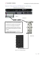
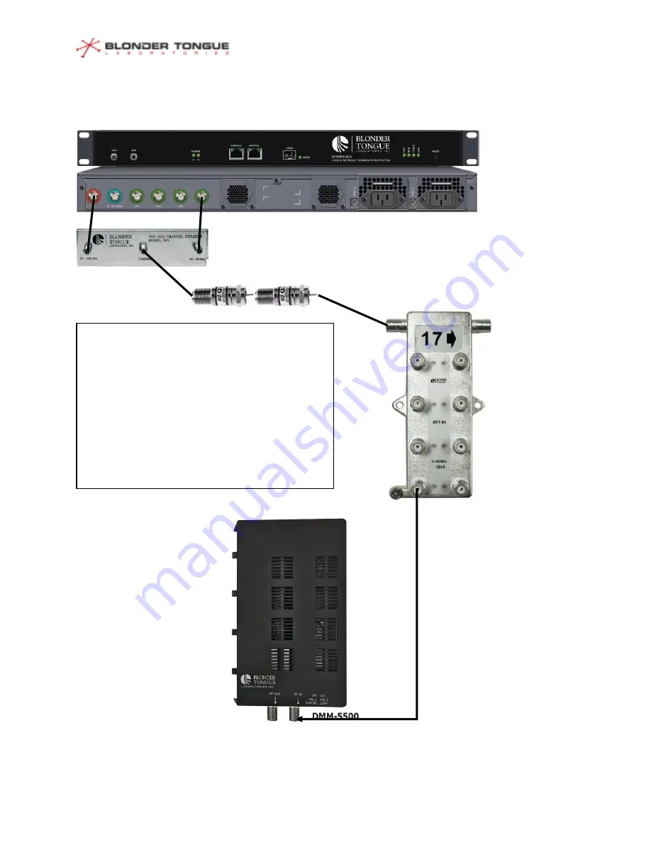
Physical setup of RF Network for Lab Testing
1. CMTS US Port 4 to Low Freq. side of Diplexer
2. CMTS DS Port to High Freq. Side of Diplexer
3. Common Port of Diplexer to Distribution
4. 40 dB total Attenuation between CMTS and
CMs for testing (including attenuators, splitters
and taps)
5. If DMM-5500 Series CM is used, must be in
conjunction with LG 5500 STB.
BT CMTS Series Lab / Test Network
Diplexer
Attenuators
Splitter/Tap
Figure 12
–
RF Test Network Setup


