


Manual
EB-MODBUS-RTU
BLOCK Transformatoren-Elektronik GmbH
Max-Planck-Straße 36-46 27283
.
Verden, Germany
10-23-17 / KRUT
Subject to technical changes
Page: 4
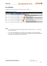
2.3.
Terminals
Communication
TxD+, TxD-, Rx+, Rx- 2/4-wire connections
Signal input
RE
24V collective reset input
Signal Contacts
13
Potential-free input
14
Channel triggered and/or switched off
24
Rated current at 90%
Care
IN+
supply voltage input +24VDC (18 - 30V)
3.
Initialization
In order for the EB-MODBUS-RTU to communicate with the PLC, the appropriate dip-
switch configuration must be made.
The MODBUS module initializes itself by applying the supply voltage to terminal
IN+
.
Functional operation is only made possible by connecting circuit breaker modules and
then applying the supply voltage to
IN+
.
After the supply voltage has been applied, all connected circuit breakers are
addressed one after the other and then selectively switched on one after the other.
Using the EB-MODBUS-RTU module, a maximum of 40 circuit breaker channels can
be addressed and managed.
Note
:
•
When applying the supply voltage to
IN+
, it is imperative that a separate GND line is
connected to one of the circuit breaker channels.
•
Initialization without a series of circuit breaker modules can lead to faulty behavior.


