3
AMB 307
Part N
o
: 9730.01
COFDM Modulator
ASI-TS
→
DVB-T (COFDM)
B
LINE
The manual instructions of the Headend Controller HCB x00 and the Bus Extender BEB x00 have to be considered!
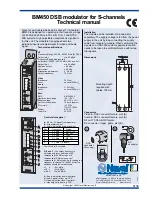
4. Front view
5. Functional description
The data stream which results from the ASI input is passed to a FIFO. All services of the resulting transport stream which shall be pro-
cessed into the COFDM modulator will be choosen by controling software of the module. The SI and PSI tables affected (i.e. the PAT,
PMT, SDT, EIT) are automatically corrected. From the Headend Controller informations are provides to generate a complete NIT (Net-
work Information Table) into the transport stream. This is required to enable the receiver (such as set-top-box) to tune in automatically.
The changed SI an PSI tables are fed into the COFDM modulator and an IF signal is generated at the output channel. There is a free
choise of frequency in the output channel from 45 to 862 MHz. On the output side, the modulator does not leak to adjacent channels.
So that errors in level can be signalled if the load fluctuates (the red LED will flash and a trap message will be sent), a reference level
is generated. Every time the level for frequency figures are programmed, automatic measurement of the refence level takes place; this
function will, however, not start until 100 seconds have elapsed after start-up of the system. This function can be enabled or disabled
in the main menu.
6. Adjustments
6.1 Adjustment with the Headend Controller
· Adjustment of the addresses at the Bus Extender BEB x00 and at the modules
· Activation of the programming mode on each module by selecting the line (BEB x00) and the module position (01... 15) at the
Headend Controller(HCB x00)
→
yellow LED illuminates until the beginning of the parameter adjustment
· Adjustment of the AMB 307 parameters (see chapter 9)
→
green LED is switched on
· After the programming the AMB 307 will be automatically switched into the operating mode
→
yellow LED flashes shortly/ green LED is switched on
6.2 Adjustment with PC/ laptop
· Prerequisite for the remote programming is an “online-connection” acording the IP standard and an ethernet connection at the
PC/ laptop
· Adjustment of the line/ position addresses at the Bus Extender BEB x00 as well as at the modules
· At the Headend Controller HCB x00 input IP address (default: 192.168.2.80)
· For “direct connection” between a PC and HCB x00 use crossover cable (RJ 45)
· For connection over a hub use a normal straight throught patch cable
· Start-up HTML browser and put in IP address as target address
· If connected correctly the web interface will be opened on the PC/ laptop and a blue LED (LINK) at the HCB x00 will be lit up.
· All adjustments of the modules are specified on the web interface.
COFDM MODULATOR
ASI-TS
DVB-T(COFDM)
ASI/ TS-MODE
burst,continuous
188,204
ASI/ TS-RATE
270/ 0.625...78
Mbps
INPUT LEVEL
200...880
mV
TV-RF OUT
45...862
MHz
OUTPUT LEVEL
max. 155
dBµV
SUPPL CURRENT 0.65
A
Type:
Part N :
AMB 307
9730.01
o
pp
COFDM MODULATOR
AMB 307
9730.01
ASI-TS
DVB-T(COFDM)
ASI/ TS-MODE burst,continuous 188,204
ASI/ TS-RATE 270/ 0.625...78 Mbps
INPUT LEVEL 200...880
mV
TV-RF OUT
45...862
MHz
OUTPUT LEVEL
max. 155
dBµV
SUPPL CURRENT 0.65
A
Type:
Part N :
o
pp
X1
ASI
IN/OUT
ASI TS input 1
LED input 1
ASI TS input 2/ output
LED input 2/ output
Operating voltage/
control bus
LED “STANDBY (red)
LED “READY“ (green)
LED “ADDR.“ (yellow)
Address selector
RF output