5
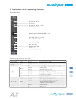
4. Explanation of the operating elements
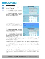
4.1 Front view
input coupler "input 1"
LED "input 1"
input coupler "input 2 / output"
LED "input 2 / output"
power connectors, operating voltage 12 V DC
status LEDs "POWER" / "SYSTEM"
status LEDs "CH1 ... CH8"
control port incl. LEDs
status LED "LOOP"
output coupler "input"
"RESET" button
output coupler "output"
4.2 Meaning of the status LEDs
Desingation
Color
Status
Meaning of the LEDs
POWER
green
constant
module is ready
-
off
module is off, operating voltage is not appllied
SYSTEM
green
constant
module is ready
flashing
software update is running
amber
constant
temperature is high, fan is activated
flashing
temperature is critical, the module will no longer work
or is forced to shut down
-
off
module is not ready
CH1 ... CH8
green
constant
all channels operate without error
amber
constant
error warnings, depending on the signal:
- input and/or output without sync
- input sync, but in low quality
flashing
hardware failure
-
off
channel is off


