


501-L00 Page 4/12
GENERAL INSTALLATION AND OPERATION
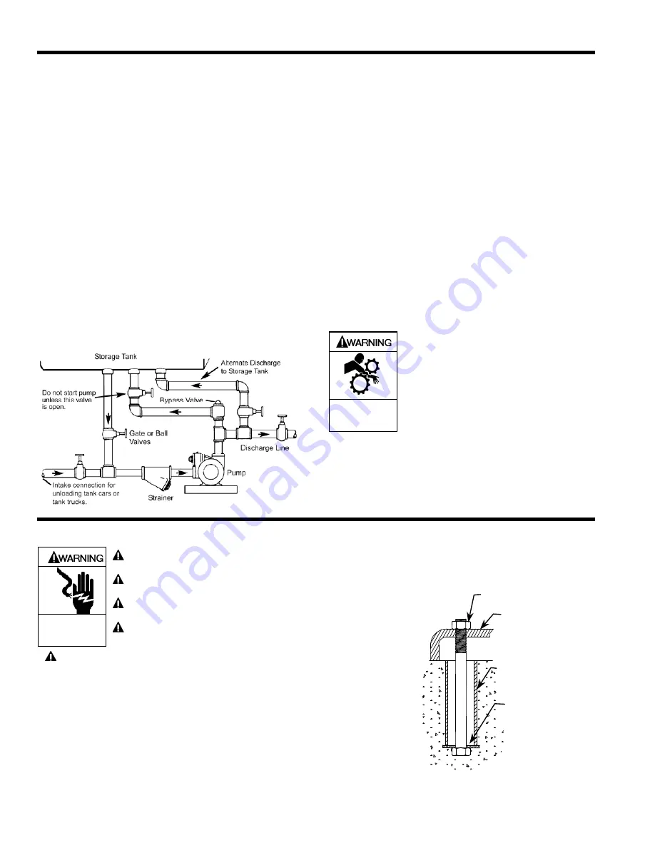
PUMP RELIEF VALVE AND BYPASS VALVE
NOTICE:
The pump internal relief valve is designed to protect the
pump from excessive pressure and must not be used as
a system pressure control valve.
For ALL liquefied gas applications, install an external bypass
valve, and any necessary piping, back to the tank. External
Bypass Valves are integral to the performance and operation
of liquefied gas pumps and are included in the boundary /
jurisdiction of the pump (Refer to Form 589).
DO NOT pipe
the bypass valve back to the intake line. The setting on the
external bypass valve must be at least 25 psi (1.7 bar) lower
than the pump internal relief valve setting. The valve and
piping must be of adequate size to accommodate the full flow
from the pump when the discharge line is closed. The non-
adjustable pump internal relief valve is factory set at
approximately 150 PSI (10.3 bar).
The 'Alternate Discharge to Storage Tank' line and manual
valve may be used to unload transports without pumps into
the storage tank. The manual valve in this line must remain
closed during all other operations.
Refer to Blackmer Bypass Valve Installation and Maintenance
Instructions for bypass valve settings and adjustments.
Figure 3 – Bypass Valve Mounting
CHECK VALVES
The use of check valves or foot valves in the supply tank is
not recommended with self-priming, positive displacement
pumps.
If the possibility of liquid backflow exists when the pump is off,
a check valve in the pump discharge piping is recommended
because the pump can motor in the reverse rotation and
create undue stress on all attached components. Never start
a pump when it is rotating in the reverse rotation as the added
starting torque can damage the pump and related equipment.
PUMP ROTATION
NOTICE:
Confirm correct pump rotation by checking the pump
rotation arrows respective to pump driver rotation.
Blackmer LGL3021 pump model has a double ended rotor
and shaft, enabling them to be driven from either shaft end.
To change rotation, rotate the pump 180 degrees so that the
opposite shaft becomes the driven shaft. The shaft protector
(186) MUST be mounted over the non-driven shaft.
Operation without guards in place can
cause serious personal injury, major
property damage, or death.
Do not operate
without guard
in place
MOTOR DRIVEN PUMPS
Install, ground and wire to local and
National Electrical Code requirements.
Install an all-leg disconnect switch near
the unit motor.
Disconnect and lockout electrical power
before installation or service
Electrical supply MUST match motor
nameplate specifications.
Hazardous voltage.
Can shock, burn or
cause death.
Motors equipped with thermal protection automatically
disconnect motor electrical circuit when overload exists.
Motor can start unexpectedly and without warning.
NOTICE:
Consult the "General Installation and Operation" section
of this manual for system information.
PUMP MOUNTING
Permanently mount the unit by securing the base plate with
adequately sized anchor bolts to a level concrete floor
following recommended industry standards (See Figure 4). A
solid foundation will reduce system noise and vibration, and
will improve pump performance. Refer to ANSI/HI standards
or a suitable pump handbook for information on typical pump
mounting and foundations. Check coupling alignment after
pump and base assembly is secured to the foundation.
BOLT
BASE
STANDARD
PIPE
WASHER
Figure 4