


501-L00 Page 10/12
MAINTENANCE
PUMP ASSEMBLY
Before reassembling the pump, inspect all parts for wear or
damage, and replace as required. Wash out the bearing/seal
recess of the head and remove any burrs or nicks from the
rotor and shaft. Remove any burrs from the liner.
Reassemble the OUTBOARD side of the pump first:
1. On 2-inch pump models, apply grease to the liner key
groove in the pump casing to hold the key (74) in place
during liner installation. Install key in groove before
starting liner (41) into pump casing (12). On 3-inch pump
models, install the liner key (74) in the groove on top of
the liner (41).
2. Align the liner key (74) with the pump casing keyway and
start the liner (41) into the casing (12) with the slots in the
liner towards the INTAKE port, and the hole pattern in the
liner towards the DISCHARGE port. Uniformly tap the
outer edge of the liner with a rubber mallet to fully insert
into the casing. NOTE: If the liner is installed backwards,
it will restrict the port openings and cause cavitation,
noise and loss of capacity.
3. Place the disc (71) against the liner (41) with the seal
cavity outward and disc relief hole located as shown in
Figure 9.
Figure 9 - Disc Relief Hole Location
4. Without installing the head O-ring or mechanical seal
components, temporarily attach the outboard head (20)
and bearing (24) to the casing (12). Install and hand
tighten two head capscrews (21), 180 degrees apart. This
head will be used to hold and align the rotor and shaft
(13) while the inboard side of the pump is assembled.
5. Remove the vanes (14) and push rods (77) from the rotor
and shaft assembly (13). Inspect for wear and damage,
and replace as follows:
a. Partially install the non-driven end of the rotor and
shaft (13) into the open side of the pump casing (12).
b. Leave part of the rotor outside of the casing (12) so
that the bottom vanes (14) can be installed and held
in place as the push rods (77) are installed in the
push rod holes of the rotor. Insert the new vanes into
the rotor slots with the rounded edges outward, and
the vane relief grooves facing TOWARDS the
direction of rotation. See Figure 8.
c. After the bottom vanes and push rods are installed,
insert the rotor and shaft (13) fully into the casing
(12).
d. Install the remaining vanes (14) into the top positions
of the rotor.
6. Install the disc (71) on the inboard side of the pump with
the seal cavity facing outward and the disc relief hole
located as shown in Figure 9.
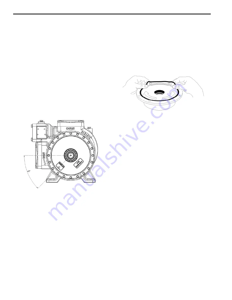
7. Install a new head O-ring (72) in the groove on the inside
face of the head (20). Lay the O-ring flat and start in on
one side of the groove, stretching ahead with the fingers,
as shown in Figure 10.
Figure 10 – Head O-ring Installation
8. MECHANICAL SEAL INSTALLATION
Rotating Assembly –
a. Apply a small amount of motor oil on the shaft
between the shaft threads and the rotor.
b. Slide the seal jacket assembly (153C) over the shaft
and into the disc cavity with the drive tangs of the
jacket towards the rotor. Rotate the jacket assembly
to engage the drive tangs in the rotor slots.
c. Install a new rotating O-ring (153E) in the rotating
seal face (153B). Align and insert the rotating
assembly into the seal jacket with the polished face
outward. Clean the polished face with a clean tissue
and alcohol.
Stationary Seat -
a. Apply a small amount of motor oil in the seal recess
of the head (20).
b. Install a new stationary O-ring (153D) in the
stationary seat (153A). Align the pin in the stationary
seat with the slot in the head recess and push the
seat fully into the seal recess with the polished face
outward. Clean the polished face with a clean tissue
and alcohol.
9. Carefully install the head assembly (20) over the shaft.
Do not contact the end of the shaft with the polished face
of the stationary seat. Rotate the head so that the drain
hole (tell-tale hole), located at the back of the bearing
cavity, faces downward when the pump is mounted for
operation. Install and uniformly tighten four head
capscrews (21) 90° apart, torquing to 30 lbs ft (40.7 Nm).
10. Hand pack the spherical roller bearing (24) with grease.
See the "Lubrication" section for recommended greases.
11. Install the bearing (24) into the head recess. Ensure the
bearing is fully and squarely seated in the head (20).
12. Turn the pump casing around and remove the outboard
head previously attached.
13. Install the outboard head (20), mechanical seal (153) and
bearing (24) as instructed in steps 6 through 11.