BLACKMER LB161B Скачать руководство пользователя страница 5

GENERAL INFORMATION


CB5A-021    page 5/24


quantity. 


On new installations, it is suggested that the valves 
and  piston  rings  be  inspected  after  the  first  few 
hundred hours of operation.  This will give an early 

indication  of  any  abnormal  problems  and  allow  for 
corrective action to be taken before a costly failure 
results.    Although  piston  ring  life  will  vary  from 
application  to  application,  wear  will  be  fairly 
consistent on subsequent sets of rings. 


INSTALLATION

NOTICE: 

Blackmer  compressors  must  only  be  installed  in 
systems designed by qualified engineering personnel.  
System  design  must  conform  with  all  applicable 
regulations  and  codes  and  provide  warning  of  all 
system hazards. 

NOTICE: 

This compressor shall be installed in accordance with the 
requirements  of  NFPA  58  and  all  applicable  local,  state 
and national regulations. 


  Install, ground and wire to local and 

National Electrical Code requirements. 

  Install an all-leg disconnect switch near 

the unit motor. 

  Disconnect and lockout electrical power 

before installation or service 


Hazardous voltage. 

Can shock, burn or 

cause death. 


Electrical supply MUST match motor nameplate 
specifications. 

  Motors equipped with thermal protection automatically 

disconnect motor electrical circuit when overload exists.  
Motor can start unexpectedly and without warning. 


LOCATION AND PIPING


Compressor  life  and  performance  can  be  significantly 
reduced  when  installed  in  an  improperly  designed 
system.    Before  starting  layout  and  installation  of  the 
piping system, consider the following: 
1.  All piping must be leak free to a pressure of 1.5 times 

the maximum system pressure. 


NOTICE:  If the  system is to be hydro-statically 
tested, the compressor MUST be isolated.  Liquid 
entering the compressor will cause damage and 
void the warranty.


2.  A  strainer  should  be  installed  in  the  inlet  line  to 

protect the compressor from foreign matter.  A #30 
mesh  screen  or  finer  is  recommended.    Strainers 

must

 be cleaned every 180 days, or more frequently 

if the system requires. 

3.  Expansion  joints,  placed  within  36"  (0.9  m)  of  the 

compressor,  will  compensate  for  expansion  and 
contraction  of  the  pipes.    Contact  the  flexible 
connector/hose 

manufacturer 

for 

required 

maintenance/care  and  design  assistance  in  their 
use. 

4.  Piping 

must

 be adequately supported to ensure that 

no piping loads are placed upon the compressor. 

5.  Both  suction  and  discharge  piping  should  slope 

down from the compressor.  The compressor should 
not be placed at a low point in the piping system. 


Discharge piping surface temperatures 
may be hot during operation (over 
158°F, 70°C).  Temperatures should be 
monitored and adequate warnings 
posted. 


Extreme Heat can 

cause personal injury 

or property damage 


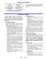
MOUNTING THE COMPRESSOR UNIT 
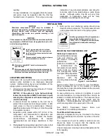
Stationary Compressors 

A solid foundation reduces 
noise  and  vibration,  and 
will  improve  compressor 
performance. 


On 

permanent  installations,  it 
is 

recommended 

the 

compressor be secured by 
anchor  bolts  as  shown.  
This  arrangement  allows 
for slight shifting of position 
to 

accommodate 

alignment 

with 

the 

mounting holes in the base 
plate. 
Set  the  anchor  bolts  in  concrete  for  new  foundations.  
When  compressors  are  to  be  located  on  existing 
concrete floors, holes should be drilled into the concrete 
to hold the anchor bolts.   
To  keep  vibration  at  a  minimum,  in  addition  to  a  solid 
concrete foundation, it is important that the concrete be 
located on a stable soil foundation.  The base must have 
complete  contact  along  its  entire  length  with  the 
foundation.    Visible  separations  will  result  in  vibrations 
which are magnified in the upper part of the unit. 

See  CB220  “Compressor  Bases,  Skids  and 
Foundations” for additional information. 

Truck Mounted Compressors 

Blackmer  compressors  may  be  mounted  to  the  frame 
rails of a truck/transport and driven by either a V-belt or 
PTO drive. 
The  compressor  should  be  solidly  mounted  and  care 
should  be  taken  to  ensure  that  the  dipstick  and 
inspections plates are readily accessible. 
Check compressor mounting bolts and baseplate anchor 
bolts regularly. 

Figure 3 - Anchor Bolt


Содержание LB161B

Страница 1: ...ALERT SYMBOL When you see this symbol on the product or in the manual look for one of the following signal words and be alert to the potential for personal injury or property damage Warns of hazards...

Страница 2: ...luid or pressure containment components during compressor operation can cause serious personal injury death or major property damage Hazardous or toxic fluids can cause serious injury Hazardous pressu...

Страница 3: ...EPLATE DATA A nameplate is attached to the side of all Blackmer compressors showing the Model No I D No and Serial No These numbers should be available when information or parts are needed for a parti...

Страница 4: ...IMIZING COMPRESSOR LIFE Life of critical compressor components such as piston rings valves and packing will vary considerably with each application installation and operating procedures Premature fail...

Страница 5: ...Strainers must be cleaned every 180 days or more frequently if the system requires 3 Expansion joints placed within 36 0 9 m of the compressor will compensate for expansion and contraction of the pip...

Страница 6: ...e of ignition in explosive atmospheres causing severe personal injury or death Hazardous gases can cause property damage personal injury or death V BELT DRIVES Most Blackmer compressors are driven via...

Страница 7: ...INSTALLATION CB5A 021 page 7 24 Figure 4 Liquid Transfer Flow Schematic Figure 5 Vapor Recovery Flow Schematic Figure 6 Typical Liquefied Gas Transfer Compressor...

Страница 8: ...h will shut off the intake line to the compressor in the event of an excessive liquid level A vacuum breaking valve is provided on the liquid trap head in case the trap closes and a vacuum develops be...

Страница 9: ...or death 2 Re check the system piping and the piping supports to ensure that no piping loads are being placed on the compressor Discharge piping surface temperatures may be hot during operation over...

Страница 10: ...ge personal injury or death The oil pump on these models will operate in either direction of crankshaft rotation 2 Verify that the suction and discharge pressures are within the expected ranges Operat...

Страница 11: ...injury Hazardous pressure can cause serious personal injury or property damage Explosive gas can cause property damage personal injury or death Extreme heat can cause personal injury or property damag...

Страница 12: ...s Internal Snap Ring Pliers Seal Replacement Feeler gauges or Depth Micrometer Piston Clearance Screwdriver Flat Blade Nameplate screws Packing Installation Pliers Rubber Mallet Arbor Press Wrist Pin...

Страница 13: ...ng the oil bring the compressor up to normal operating temperature Remove the crankcase drain plug and drain the oil into an adequately sized container Remove the oil pickup screen and clean in a suit...

Страница 14: ...and cylinder O rings from the crosshead guide or distance piece 6 Packing Box Removal a Using an adjustable spanner wrench remove the packing box hold down rings Replace the nylon locking inserts in...

Страница 15: ...the bearing with grease g Set the top of the connecting rod over the crankshaft journal Replace the connecting rod cap with the dots on the connecting rod and cap on the same side h Start the nuts on...

Страница 16: ...e threading the piston clockwise onto the rod Tighten with the 3 adjustable spanner wrench d Follow this same procedure for the second piston e Rotate the crankshaft by hand a number of times to verif...

Страница 17: ...rop the liquid relief ball and spring into the head interior 4 Discharge valve Remove the discharge valve cage valve assembly and gasket 5 Inspect the valve for wear or breakage 6 Ensure that the old...

Страница 18: ...e the valve hold down screw is removed from the cover plate then place the cover plate and new O ring in position f Install the valve cover plate capscrews and tighten per Table 7 Bolt Torque g Instal...

Страница 19: ...o Figures 12 and 13 for proper TYPE 1 component location and orientation 4 Single Seal Packing Box Assembly a Install the lower retainer ring b Install the packing rings spring washers and the upper r...

Страница 20: ...last washer to compress the seal spring slightly LB602C Attach the S3R seal cup assembly to the bottom of the packing box c Insert the oil deflector ring excluding LB602 through the top of the packin...

Страница 21: ...bearing cone onto each end of the crankshaft with the tapered end outward The bearing race should rest against the shoulder on the crankshaft e Lubricate the bearings with grease 8 Install the cranksh...

Страница 22: ...age to the compressor may occur Complete compressor disassembly and replacement of rod packing bearings and other parts may be required 1 Keep a written record storage procedures performed preferably...

Страница 23: ...lved bypass line between the suction and discharge lines may be necessary 6 7 Knocks or Other Noises 10 Loose Valves Tighten valve hold down screws 11 11 Worn Internal Parts Inspect through inspection...

Страница 24: ...CB5A 021 page 24 24 1809 Century Avenue Grand Rapids Michigan 49503 U S A 616 241 1611 Fax 616 241 3752 www blackmer com...

Отзывы: