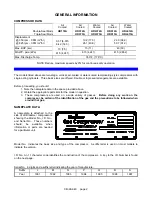
BLACKMER HD172A Скачать руководство пользователя страница 3

CB-9A-040     page 3 

 GENERAL 

INFORMATION


HD TWO-STAGE COMPRESSORS


ID NUMBER KEY


P


B


B


F


M


1


T


A


1 A A


VALVES 

Code  

Fields 


TNT-12 steel 

BE 

 1 & 2 


TNT-12 

steel 

w/ 

Unloaders 

BF   


Ductile 

Iron 

PEEK 

PB   


DI/PEEK 

w/ 

Unloaders 

PC   


TNT-12 

DI/PEEK 

PE   


TNT-12 

DI/PEEK 

w/ 

Unloaders 

PF   


Stainless Steel 

SB 


SS 

w/ 

Unloaders 

SC   


 O-RINGS 


 Field 3 


Buna-N 

B   


Neoprene 

N   


PTFE 


FKM 


Ethylene-Propylene 

E   


GASKETS 


Field 

4                           

Aluminum 


Iron 


Copper 

C   


 PISTON RINGS 


 Field 5 


Glass & Moly Filled 


Poly Filled PTFE 


SEAL 

(PACKING) 

ORIENTATION 


Field 

6                           

All Lips up 


Top Lips Down, Bottom Up 
   Tube to Stage 1 outlet 


Top Lips Up, Bottom Down 


Top Lips Down, Bottom Up 
   Tube to Stage 2 outlet 


Up, Down, Up 


Down, Down, Up 


Down, Up, Up 


SEAL 

MATERIAL 


Field 

7                           

PTFE 


 CYLINDER & HEAD 


 Field 8 


Ductile Iron 


TNT-12 DI Cylinder 


TNT-12 

DI 

Cyl. 

Head 

C   


 PISTON RODS 


 Field 9 


Chrome Plated Steel 


CrO

2

 Coated Steel 


Black Surface Steel 


 CRANKSHAFT & OIL FILTER 


 Field 10 


Standard 

A   


Spin-on Oil Filter 


OTHER 

 Field 11 


Notes: 

A 'Z' in any field indicates a non-standard option. 


No model is available with all shown options. 

Содержание HD172A

Страница 1: ...TICALLY TESTED COMPRESSOR MUST BE ISOLATED WATER ENTERING THE UNIT CAN CAUSE CORROSION AND DAMAGE NOTE NAMEPLATE DATA HERE MODEL HD ID SERIAL NUMBER TABLE OF CONTENTS GENERAL INFORMATION 2 Compressor...

Страница 2: ...you should 1 Note the nameplate data in the space provided above 2 Obtain the appropriate parts lists for the model in question 3 These compressors are used on a wide variety of gasses Before doing an...

Страница 3: ...5 Glass Moly Filled M Poly Filled PTFE A SEAL PACKING ORIENTATION Field 6 All Lips up 1 Top Lips Down Bottom Up Tube to Stage 1 outlet 2 Top Lips Up Bottom Down 3 Top Lips Down Bottom Up Tube to Stag...

Страница 4: ...is suggested that the valves and piston rings be inspected after the first few hundred hours of operation This will give an early indication of any abnormal problems and allow for corrective action to...

Страница 5: ...eric Pressure or above Vacuum to 25 psia Under 5 psia Service General Gas Transfer Toxic Flammable or otherwise Hazardous Gases General Gas Transfer Special Upper Distance Piece Connections Plugged Pu...

Страница 6: ...CB 9A 040 page 6 GENERAL INFORMATION SEAL ORIENTATION DOUBLE SEAL COMPRESSORS SEAL ORIENTATION ALL TRIPLE SEAL COMPRESSORS...

Страница 7: ...l port allowing for the use of an optional electric float switch which provides protection to the compressor by stopping the compressor when a high liquid level is present in the liquid trap The elect...

Страница 8: ...hor bolts be set in concrete When compressors are to be located on existing concrete floors holes should be drilled into the concrete to hold the anchor bolts NOTE To keep vibration at a minimum in ad...

Страница 9: ...unning time Also retighten all holddown bolts flywheel bolts etc after 60 minutes running time MAINTENANCE MAINTENANCE AND TROUBLESHOOTING MUST BE DONE BY AN INDIVIDUAL EXPERIENCED WITH COMPRESSOR MAI...

Страница 10: ...iver Flat Blade Nameplate screws Packing Installation Pliers Rubber Mallet Arbor Press Wrist Pin Removal Bearing Puller Crankshaft Bearings Torque Wrench 0 to 45 ft lb range Various Hoist useful Cylin...

Страница 11: ...Y Below 0 F 18 C 0 to 32 F 18 to 0 C 32 to 80 F 0 to 27 C 80 F 27 C and above SAE 5W SAE 10W SAE 20W SAE 30W Series 170A 370A 610A Quarts 2 3 6 To change the oil drain the crankcase then clean the oil...

Страница 12: ...the piston rods The upper packing box O rings will slide off with the packing boxes For disassembly of the packing boxes refer to Packing Replacement 11 After removing the packing boxes remove the lo...

Страница 13: ...e b Lubricate the inside bore of the crosshead guide with light oil c Set the crosshead guide over the piston rods and the crossheads and slowly lower it against the crankcase Make certain that the cr...

Страница 14: ...ue Table in an alternating pattern h It is important that the proper number of shims be installed under the piston To check rotate the flywheel by hand to bring one piston to the top 1 Measure the dis...

Страница 15: ...mportant to install the suction and discharge valves in the correct location in the cylinder head NOTE The valves may be removed without removing the cylinder head from the cylinder Be sure to remove...

Страница 16: ...r and retainer ring Typical Valve Assemblies 4 To reinstall valves a Install a new valve gasket into the cylinder head remove any old gaskets b Install the valve assembly in the cylinder head Make sur...

Страница 17: ...wn screw and tighten according to the Bolt Torque Table f Install the valve cap or unloader assembly and O ring A little oil or grease on the O ring will help hold it in place during installation 5 Af...

Страница 18: ...ring Note To ease installation on the second retainer ring use a screwdriver handle and press on the last washer to compress the seal spring slightly c Two seal packing boxes only Insert the oil defl...

Страница 19: ...g cone onto each end of the crankshaft with the tapered end outward The bearing race should rest against the shoulder on the crankshaft e Lubricate the bearings with grease 8 Install the crankshaft th...

Страница 20: ...mp ring over the rotor Place the cover O ring into the bearing carrier do not place it on the oil pump cover 6 Orient the oil pump cover with the upper direction arrow the one labeled TOP for the prop...

Страница 21: ...pressurized to prevent air or moisture from entering the unit NOTICE Tag the unit with a warning that it is pressurized 3 If a purge gas is not available fog oil into the compressor suction while rot...

Страница 22: ...9 9 Low Oil Level Check and fill as necessary 10 10 Dirty Inlet Strainer Clean Inlet Strainer Gas Leaking From Crankcase Breather 11 Faulty Worn Packing Replace Packing 12 12 Piston Rod Scored Replace...

Страница 23: ...CB 9A 040 page 23 NOTES...

Страница 24: ...1809 Century Avenue Grand Rapids Michigan 49503 U S A 616 241 1611 Fax 616 241 3752 1108 So Portland Avenue Oklahoma City 73108 U S A 405 942 6622 Fax 405 942 2855...

Отзывы: