


CB-9A-040 page 13
MAINTENANCE
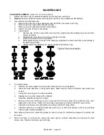
COMPRESSOR ASSEMBLY
Compressor assembly is generally the opposite of compressor disassembly. Before reassembling, clean each
part thoroughly. Check all machined surfaces for burrs or roughness, and file lightly if necessary.
NOTE:
If any of the O-rings or gaskets are removed or disturbed during service, it is recommended they be
replaced with new.
1.
CRANKCASE
ASSEMBLY
After replacing the crankshaft, bearing carrier, and bearing cover plate (see "Bearing Replacement"), the
connecting rod and crosshead can be installed.
a.
To attach the connecting rod to the crosshead assembly, first coat the wrist pin, the wrist pin bore in
the crosshead assembly, and the wrist pin bushing in the connecting rod with grease.
b.
Start the wrist pin in the bore of the crosshead assembly and tap lightly until the pin begins to project
through to the inside of the crosshead assembly.
c.
Slide the connecting rod up inside of the crosshead assembly and align the bushing with the wrist
pin.
d.
Lightly tap the wrist pin through the connecting rod until it is centered in the crosshead assembly.
NOTE: The wrist pin should be snug in the crosshead assembly. The connecting rod should rotate
freely on the wrist pin, but should not be loose.
e.
Dip the wrist pin plugs in grease and press them in place.
f.
Place the bearing halves into each half of the connecting rod, aligning the bearing tangs with the
slots in the connecting rod. Coat the bearing with grease.
g.
Set the top of the connecting rod over the crankshaft journal. Replace the connecting rod cap,
remembering that the dots on the connecting rod and cap must be on the same side.
h.
Start the nuts on the connecting rod bolts and torque per the Bolt Torque Table.
i.
Follow this same procedure for the opposite connecting rod.
2.
CROSSHEAD
GUIDE
a.
Place the crosshead guide gasket on top of the crankcase.
b.
Lubricate the inside bore of the crosshead guide with light oil.
c.
Set the crosshead guide over the piston rods and the crossheads, and slowly lower it against the
crankcase. Make certain that the crosshead assemblies are started straight in the bores of the
crosshead guide to prevent binding when lowering the crosshead guide into position.
d.
Install the crosshead guide capscrews
loosely
.
3.
Fill the crankcase with oil. See "Lubrication" for proper amount. Squirt oil into the crankshaft, roller
bearings, crankshaft journals, and crosshead assemblies so they will have lubrication at start up.
4.
Attach the inspection plate and the inspection plate gasket to the crankcase.
5.
PACKING
BOX
ASSEMBLIES
Before installing the packing boxes into the crosshead guide, inspect the piston rods for scoring or
roughness. Remove any burrs or sharp edges. Lubricate the piston rods and packing box O-rings with
light oil.
Do not damage the packing when starting it over the rod. Use of a Blackmer packing
installation tool is recommended.
a. Place the packing installation cone (if available) on the top of the piston rod.
a. Insert the lower packing box O-ring into the crosshead guide.
b. Start the packing box assembly, short end down, over the piston rod.
c. After the lower set of packing is started over the piston rod, make sure the oil deflector ring is properly
aligned (with the flat side down) over the piston rod. Use the hole in the side of the packing box to
center the deflector ring. Once the deflector ring is over the rod, the packing box can be fully inserted.
d. Install the upper packing box O-ring on the end of the packing box.
e. Place the packing box spacer ring over the O-ring.
f.
Install the packing box retainer ring with new nylon locking inserts, and tighten.
g. Remove the packing installation cone, if used.
h. Repeat the above steps for the remaining packing box.
The following applies to Triple-Seal Models only.
i.
Install new O-rings in the bottom of the upper distance piece. A small amount of grease may be used
to hold the O-rings in place during assembly.
Содержание HD172A
Страница 23: ...CB 9A 040 page 23 NOTES...


