


INSTALLATION
CB9A-005 page 9/28
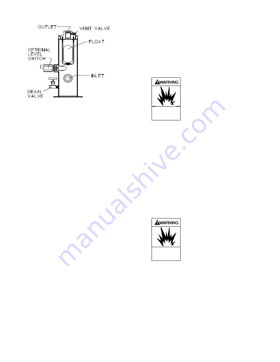
2. The above trap is fitted with a port allowing the use
of an electric float switch which protects the
compressor by stopping the compressor when a high
liquid level is present in the liquid trap. The electric
float switch may be used with or without the
mechanical float described above.
3. For additional protection, a larger ASME code
stamped vessel is available. This liquid trap is
typically fitted with one or two electric float switches
for both a high liquid level shut down and alarm
signal, a relief valve, and a manual drain valve. This
type trap is needed if level gauges or automatic drain
systems are to be used.
4-WAY VALVES
Many liquefied gas compressors are used for both liquid
transfer and vapor recovery operations. An optional 4-
way valve is used to reverse the direction of flow through
the system when changing from liquid transfer to vapor
recovery. Both lubricated and non-lubricated models are
available. Lubricated models should be lubricated every
6 months.
TEMPERATURE SWITCHES
Excessive discharge temperature is a leading cause of
premature component failure and is often an early
warning sign of impending problems.
Optional temperature switches should be installed with a
thermowell as close to the compressor discharge as
possible. The switch should be set to actuate at a
temperature just above the maximum operating
temperature of the compressor.
ATEX compliant compressors
must
have a temperature
switch installed.
LOW OIL PRESSURE SWITCHES
Loss of crankcase oil pressure is a rare occurrence, but
can result in costly damage. An optional low oil pressure
switch set at about 15 psig (1 bar-g) may be installed to
shut down the compressor in the event of a lubrication
failure. A 10 second delay timer should be used to lock
the low oil pressure switch out during compressor
startup.
PRESSURE SWITCHES
Pressure switches may be installed in the suction or
discharge gas stream as protective devices, for
compressor control, or for other uses varying with each
application and system design.
PRESSURE GAUGES
Install pressure gauges in the discharge and inlet lines to
verify actual suction and discharge pressures.
Optional liquid trap level switches,
temperature switches, pressure
switches or other electrical devices
must be properly specified for
applications using explosive gases.
Hazardous gases
can cause property
damage, personal
injury or death
SUCTION VALVE UNLOADERS
Compressors may be fitted with suction valve unloaders
to provide loadless start or capacity control functions.
Blackmer unloaders are basically a piston and a plunger
atop the suction valve. When pressure is applied to the
top of the unloader piston, it and the plunger move
downward, pushing the suction valve off its seat and
unloading the compressor. When the pressure signal is
removed, the unloader spring pushes the piston and
plunger back up and the suction valve will resume
normal operation.
1. In order for the unloaders to function, the unloader
pressure must be at least 30 psi (2.1 Bar) above
suction pressure.
2. Do not operate unloaders for longer than 10
minutes as gas recirculation through the suction
valves will cause overheating.
Excessive gas recirculation using
suction valve unloaders can be a source
of ignition in explosive atmospheres
causing severe personal injury or death
Hazardous gases
can cause property
damage, personal
injury or death
3. Do not place a restrictive device such as a back
check valve in the suction line near the compressor.
If such a device must be installed, the volume in the
piping between the device and the compressor
must be at least 10 times the cylinder swept
volume.
Fig. 4 –
Typical Liquid Trap


