111-F00 Page 10/16
MAINTENANCE:
PUMP ASSEMBLY
Before reassembling the pump, inspect all component
parts for wear or damage, and replace as required. Wash
out the bearing/seal recess of the head and remove any
burrs or nicks from the rotor and shaft.
Reassemble the BEARING Components first:
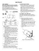
To aid in the replacement of the sleeve bearing (24)the
creation and use of a tool similar to the one shown in Figure
8 may be useful.
Figure 8 – Sleeve Bearing Installation
Bearing Bore
Dia. “C”
Tool
Dim “A”
Tool
Dim “B”
1.26 in.
(32mm)
2.05 in.
(52 mm)
1.25 in.
(31.75 mm)
1. Inspect the sleeve bearing (24) for wear or damage and
replace as required.
To replace sleeve bearing:
a. Using an appropriately sized arbor press, remove
the old bearing (24) from the bearing housing (57).
b. To aid installation and prevent bearing damage, coat
the bearing (24) with grease and place it on the face
of the bearing housing (57). Align the seam in the
bearing at 12:00 position (opposite the pump foot)
c.
Using an arbor press, press the bearing (24) into the
housing (57) until it is
flush
with the face of the
bearing housing.
NOTE: Ensure the bearing does not become misaligned
during the pressing motion
2. Inspect the ball bearing (24C) for wear or damage and
replace as required.
To replace ball bearing:
a. Using an appropriately sized arbor press, remove
the old bearing (24C) from the bearing adjuster
(188). Discard the old bearing after removal.
b. To aid installation and prevent bearing damage, coat
the bearing with grease and place it on the face of
the bearing adjuster (188)
c.
Using an arbor press which only contacts the outer
race of bearing, press the OD of the bearing into the
bearing adjuster until fully seated.
3. Cylinder O-ring installation
a. Install a new O-ring (71) over the dowel of the Bearing
housing (57).
4. Reassemble the cylinder to the bearing housing
positioning it for the desired flow direction (
see Flow
Direction Options
). Install cap screws (21A) through the
bearing housing into the cylinder. Torque per Table 1.
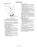
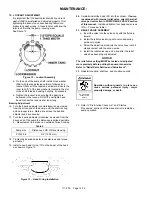
FLOW DIRECTION OPTIONS
NO vane or rotational changes are required to reverse
flow direction for the PV(S)6, 8. The pump will have a
CLOCKWISE ROTATION regardless of flow direction.
For the pump to operate with the INTAKE port on the
RIGHT
as viewed from the driven end of the pump,
position the cylinder with the pressure ports pointing up in
relation to the feet. See Fig 4.
For the pump to operate with the INTAKE port on the
LEFT
as viewed from the driven end of the pump, position
the cylinder with the pressure ports pointing down in
relation to the feet. See Fig 5.
TO REVERSE FLOW DIRECTION
Loosen cylinder cap screws (21A) to loosen cylinder from
drive housing. Rotate cylinder on drive housing 180 degrees.
Install cap screws (21A) through bearing housing and torque
per table 1.
5. Assemble Rotor and Shaft
(if disassembled).
a. Loosely assemble rotor (13B) on to shaft (13A)
securing with socket cap screws (13C).
DO NOT damage the OD surface finish of the rotor
and shaft.
b. Secure a piece of steel sized to fit the width and length
of a vane slot in a vise or other holding device. Place
the loosely assembled rotor and shaft on to the piece
of steel in one of the vane slots; completely filling the
entire vane slot.
c. Hold the assembly securely without damaging the OD
of the rotor or shaft.
d. Tighten the socket cap screws (13C). Torque per
Table 1.
Figure 10 – Rotor / Shaft Assembly Torque
Содержание 111-F01
Страница 15: ...111 F00 Page 15 16 NOTES...


